
Views: 0 Author: Site Editor Publish Time: 2026-09-08 Origin: Site


Modern Battery Energy Storage Systems (BESS) pack unprecedented energy density into highly compact physical footprints. This rapid escalation in energy density brings a corresponding, exponential increase in available fault currents. Inadequate DC circuit protection introduces catastrophic operational and financial risks to any energy project. We are talking about severe thermal runaway events, dangerous arc flash incidents, extended grid downtime, and ultimately, completely uninsurable assets. Standard AC protection strategies completely fail under these extreme DC fault conditions. You need specialized battery energy storage circuit protection to handle these unique electrical loads safely. This comprehensive guide provides a technical evaluation framework for engineers, system integrators, and project managers. You will learn how to specify, evaluate, and implement robust protection architectures. We will cover exactly how to meet strict safety standards, ensure long-term asset insurability, and maintain peak system efficiency without compromising site safety.
Electrical protection in energy storage environments requires a fundamental shift in engineering philosophy. The physical behavior of direct current under fault conditions presents hurdles unseen in traditional alternating current networks. Field engineers quickly learn that applying AC logic to DC systems results in catastrophic equipment failure.
AC power naturally crosses zero volts 100 or 120 times per second depending on your grid frequency. This natural zero-crossing helps extinguish electrical arcs almost automatically. DC power provides a continuous, unyielding flow of current. Extinguishing a DC fault requires forcing the current to zero manually. You must use specialized magnetic arc-chutes or high-speed melting elements to break the circuit safely. If you apply standard components to a 1500V DC fault, the arc will simply sustain itself across the open contacts until the surrounding equipment melts into slag.
Lithium-ion battery banks store massive amounts of potential energy with extremely low internal resistance. During a dead short circuit, these battery banks deliver massive fault currents instantaneously. We often see these available fault currents exceed 100kA in under five milliseconds. Standard commercial breakers will simply weld shut or explode violently under this sudden mechanical and thermal stress. Protection devices must possess exceptionally high interrupting ratings to survive and clear these events. Furthermore, the physical busbars and cabling must be braced to withstand the immense magnetic forces generated during these short-circuit events.
BESS units constantly alternate between charging from the grid and discharging back into it. Protection devices must handle continuous current flow in both directions seamlessly. They must also interrupt fault conditions bidirectionally without any performance derating. Many legacy DC components were designed for unidirectional flow, such as standard solar photovoltaic applications. If you install a unidirectional solar fuse in a bidirectional battery system, it will likely fail prematurely or fail to clear a reverse-current fault. Energy storage requires true bidirectional capability to maintain safety during complex charge and discharge cycles.
Diverse grid applications introduce varying thermal stresses on electrical infrastructure. Frequent cycling for grid stabilization and peak shaving creates continuous thermal expansion and contraction within the conductors. This constant thermal cycling fatigues the bimetallic strips inside circuit breakers and the silver elements inside fuses. Prolonged standby periods for backup power introduce entirely different fatigue profiles on protection components. Engineers must account for these dynamic duty cycles when sizing components to prevent premature mechanical failure or nuisance tripping in the field.
The ultimate success metric for any energy storage safety system is speed. The protection system must clear electrical faults instantly. It must act significantly faster than the time it takes for localized cell heating to trigger a system-wide thermal runaway event. Once a lithium-ion cell exceeds approximately 150°C, thermal runaway begins and propagates rapidly from cell to cell. High-speed circuit protection acts as the primary barrier preventing an electrical fault from becoming an uncontrollable chemical fire. Every millisecond counts when isolating a shorted module.
Selecting the right hardware forms the foundation of a safe energy storage facility. Each component category serves a distinct role in the overall safety architecture. You must evaluate these components based on their specific DC performance metrics, not their AC equivalents.
Fuses act as the primary defense for short-circuit protection. They offer ultra-fast clearing times that mechanical devices simply cannot match. When evaluating fuses, you must compare aR (partial range) versus gR (full range) semiconductor fuses. Partial range fuses provide excellent short-circuit protection but require a separate device, like a contactor or breaker, to handle low-level overload conditions. Full range fuses handle both short circuits and overloads. Modern utility-scale systems require voltage ratings up to 1500V DC and exceptionally high breaking capacity. You must also evaluate the fuse's melting integral (I2t) to ensure it clears the fault before downstream components sustain damage.
Breakers provide reliable overload protection, manual switching capabilities, and immediate resettability. Mechanical clearing times are naturally slower than high-speed fuses. However, the ability to reset a breaker after a minor overload saves significant maintenance time and operational downtime. You must specify DC-specific magnetic trip units to handle the unique arc-clearing demands of battery systems. These DC breakers utilize permanent magnets within their arc chutes to actively blow the DC arc into splitter plates, stretching and cooling the arc until it extinguishes. Never repurpose AC breakers for DC applications.
These components ensure safe electrical isolation for maintenance personnel. They also facilitate automated load shedding directed by the facility control system. You need to specify clearly whether you require load-break or non-load-break capabilities. Load-break switches can safely interrupt the flow of current during operation. Non-load-break switches must only be opened when the circuit is completely de-energized. Proper integration of these contactors with emergency stop (E-stop) loops is non-negotiable for overall site safety.
SPDs mitigate transient overvoltages originating from external lightning strikes or internal grid switching events. You must properly size and select Type 1 versus Type 2 DC SPDs based on their location within the system. Place Type 1 SPDs at the main inverter interface to handle massive external surges. Install Type 2 SPDs directly on the battery racks to manage internal voltage spikes generated by contactor switching. These devices utilize Metal Oxide Varistors (MOVs) to shunt excess voltage safely to ground.
| Component Feature | High-Speed DC Fuses | DC Circuit Breakers (MCCB/ACB) |
|---|---|---|
| Primary Function | Ultra-fast short circuit interruption | Overload protection and switching |
| Clearing Speed | Extremely fast (1-5 milliseconds) | Moderate (20-50 milliseconds) |
| Resettability | Single-use (requires physical replacement) | Reusable (manual or remote reset) |
| Interrupting Rating | Very High (often >100kA to 250kA) | High (requires careful specification, typically 50kA-100kA) |
| Arc Extinguishing Method | Silica sand filler quenches the melting element | Magnetic arc chutes and splitter plates |
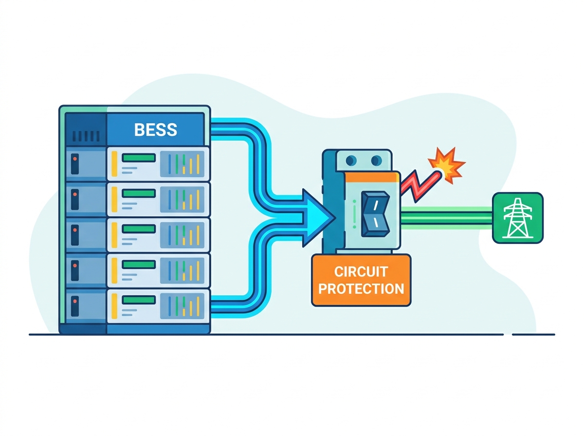
Relying on a single point of protection leaves a facility vulnerable to catastrophic failure. Best practices dictate a multi-tiered architecture. This approach isolates faults at the lowest possible level, preserving the operational integrity of the wider system. You must design the system so that a localized fault does not take the entire power plant offline.
The primary objective here is to isolate internal cell or module faults before they impact the entire battery rack. You achieve this by integrating low-amperage, high-speed fuses directly within the battery modules. This highly granular approach prevents localized cell failures from escalating into rack-wide events. It acts as the first line of defense against internal short circuits caused by manufacturing defects or physical damage to individual cells.
You must protect the main DC bus from a failing rack. At the same time, the rest of the healthy energy storage system needs to continue operating normally. Implement DC MCCBs or fused disconnects at the rack level to achieve this isolation. Ensure strict coordination with rack-level BMS contactors. The BMS should handle normal operational switching, while the breaker or fuse remains dedicated exclusively to fault interruption. If a rack controller fails, the hardware protection must step in immediately.
This upper tier protects the main DC bus and the Power Conversion System (PCS). It guards against massive external grid faults or severe internal system failures. Deploy heavy-duty ACBs or large-format square-body fuses at this critical junction. Modern 1500V DC system architectures require robust, high-capacity components here. These devices must handle the combined fault current contribution of all connected battery racks simultaneously. Sizing these components requires a detailed short-circuit study of the entire facility.
Physical damage to conductors often leads directly to severe electrical faults. You must ensure the safe routing of all high-current DC lines. Evaluate buried versus free-air cabling strategies carefully based on site conditions. Proper cable trays, adequate bend radii, and robust conduit selection act as the very first physical layer of circuit protection. Poor wire management inevitably leads to insulation degradation and subsequent ground faults. You must strictly adhere to cable tray fill ratios to prevent heat buildup in bundled DC cables.
Designing a robust protection scheme is not just about engineering best practices. It is a strict regulatory requirement. Failing to adhere to established safety standards renders a project non-compliant, hazardous, and impossible to commission.
These standards strictly dictate the safety requirements of the overall energy storage system. UL 9540 covers the overarching safety of the integrated system. UL 9540A specifically evaluates the fire safety hazards of thermal runaway propagation at a highly granular level. The test results directly impact the required speed and reliability of your circuit protection. They dictate the necessary spatial separation between racks and the exact fault-clearing speeds required to prevent cell-to-cell fire propagation. If your protection devices are too slow, you will fail the UL 9540A propagation test.
The National Fire Protection Association outlines strict rules for the installation of stationary energy storage systems. NFPA 855 focuses heavily on spatial clearance, electrical isolation, and emergency disconnect requirements. Compliance ensures that first responders can interact safely with the system during a fire or electrical event. It mandates clear labeling, accessible isolation points for all DC circuits, and specific Maximum Allowable Quantities (MAQ) of stored energy per fire area.
Global deployments require strict adherence to international standards. IEC 62933 governs electrical energy storage systems worldwide. It focuses heavily on overall system safety, integration parameters, and rigorous environmental testing protocols. Equipment specified for international projects must carry appropriate IEC certifications to ensure global compliance and operational safety. You cannot simply export a UL-listed system to Europe or Asia without verifying IEC compliance for all protection components.
Engineering a protection architecture requires balancing competing priorities. System designers must weigh performance, physical constraints, and long-term operational impacts. There is no single perfect component; you must select the right tool for the specific application.
Engineers must balance the need for ultra-fast thermal event prevention against operational uptime. Selecting ultra-fast fuses prevents thermal runaway effectively. However, transient inrush currents during PCS startup can cause unnecessary downtime if the protection is too sensitive. You must conduct detailed coordination studies to select a trip curve that ignores harmless transients while reacting instantly to genuine faults. A nuisance trip on a 100MW facility causes massive revenue loss.
High-amperage DC components occupy significant physical space within tight enclosures. Larger components dissipate heat much better than compact ones, extending their operational lifespan. Unfortunately, they also consume valuable volumetric energy density within the BESS container. Engineers must optimize the physical layout to ensure adequate cooling without sacrificing too much battery capacity. Forced air cooling or liquid cooling systems often become necessary to manage the heat generated by high-current breakers and fuses.
Fuses offer a significantly lower initial purchase cost compared to mechanical breakers. However, they require higher replacement labor and cause longer system downtime after a fault occurs. DC circuit breakers demand a higher capital expenditure upfront. They offset this initial cost with much easier resettability and lower long-term maintenance labor. Facilities with high anticipated fault frequencies, or those located in remote areas with long technician response times, often benefit from the breaker approach.
Investing in premium, multi-layered protection architectures requires higher initial capital outlays. This investment directly correlates with lower specialized insurance premiums over the life of the asset. It drastically reduces enterprise risk by preventing total asset loss during a fire. Insurers closely scrutinize the quality of DC protection when underwriting utility-scale energy storage projects. A poorly protected system will either face exorbitant premiums or be denied coverage entirely.
| Design Strategy | Initial Capital Expenditure | Risk Mitigation & Insurance Impact |
|---|---|---|
| Single-Tier Protection (Fuses Only at Inverter) | Lowest | High risk of total system loss. Difficult to insure. |
| Dual-Tier (Rack Breakers + Inverter Fuses) | Moderate | Standard risk profile. Generally acceptable to insurers. |
| Multi-Tier (Module Fuses + Rack Breakers + Inverter ACBs) | Highest | Lowest risk profile. Qualifies for premium insurance rates. |
Even the best-designed architectures face risks during deployment and daily operation. Identifying these risks early allows for effective mitigation strategies in the field.
Servicing high-voltage DC systems poses severe risks to maintenance personnel. An accidental arc flash can cause fatal injuries and destroy equipment in a fraction of a second. DC arc flashes are particularly dangerous because they do not self-extinguish.
Mitigation: Specify dead-front designs and remote racking mechanisms to keep personnel away from live busbars. Enforce strict Lockout/Tagout (LOTO) procedures for all maintenance staff. Require the use of properly rated Personal Protective Equipment (PPE), including arc-rated suits and face shields, at all times when opening enclosures.
Outdoor BESS containers face extreme temperature fluctuations, high humidity, and constant vibration. These environmental factors severely affect protection device calibration and mechanical reliability over time. Condensation can cause tracking across insulation, leading to ground faults.
Mitigation: Require comprehensive environmental testing data from all component manufacturers. Implement proper enclosure climate control using dedicated HVAC systems to maintain stable operating temperatures for sensitive electrical gear. Install anti-condensation heaters inside breaker compartments.
Software-driven BMS trip curves can easily conflict with hardware fuse or breaker curves. This mismatch leads to unpredictable system behavior during a fault, where the hardware trips before the software can log the event, or vice versa. This creates a diagnostic nightmare for field technicians.
Mitigation: Mandate rigorous time-current curve (TCC) coordination studies during the initial engineering phase. Ensure the BMS handles minor overloads and thermal warnings, while the hardware serves as the definitive backstop for severe short circuits.
Software-reliant systems remain highly vulnerable to hacking or physical tampering. A compromised BMS can be instructed to ignore critical fault data, leading to a catastrophic fire. Malicious actors can force contactors closed during a fault condition.
Mitigation: Implement robust physical perimeter security and strict network firewalls. Position hardware circuit protection as the ultimate, un-hackable fail-safe against malicious BMS overrides. A physical fuse will always blow during a short circuit, regardless of what the software dictates. You cannot hack a melting piece of silver.
You cannot afford to cut corners on battery energy storage circuit protection. The financial liability of a fire, a catastrophic failure, or an uninsurable asset far outweighs the premium of high-tier protection components. A multi-tiered, meticulously coordinated protection architecture is the only way to ensure the long-term viability of an energy storage asset. Relying on passive hardware fail-safes guarantees that your system remains protected even if software controls fail.
Select your component vendors based strictly on verified third-party testing from UL or IEC. Demand comprehensive time-current curve data for every device. Prioritize manufacturers with specific, proven expertise in high-capacity 1500V DC applications. Avoid generic components that lack rigorous energy storage certifications.
Take the following actions to secure your energy storage assets:
A: AC power naturally crosses zero volts, which helps extinguish electrical arcs automatically. DC power provides a continuous current without a zero-crossing. Therefore, DC circuit protection requires specialized arc-extinguishing mechanisms, such as magnetic arc chutes or high-speed melting elements, to safely break the circuit and prevent equipment meltdown.
A: Sizing a BESS fuse requires calculating the continuous load current and the maximum available fault current of the battery bank. You must also apply ambient temperature derating factors based on the enclosure environment. Finally, select a fuse with a clearing time fast enough to prevent cell thermal runaway.
A: Standard AC breakers rely on the natural zero-crossing of AC current to quench arcs. If applied to a high-voltage DC fault, an AC breaker will fail to clear the continuous DC arc. This results in rapid component meltdown, catastrophic system failure, and severe fire risks.
A: The BMS provides active, software-based monitoring of cell voltage, temperature, and current. It controls contactors for normal operational switching. Fuses and breakers provide passive, un-hackable hardware protection. They act as the ultimate fail-safe if the BMS software fails or is compromised by external threats.
A: UL 9540A evaluates the fire safety hazards of thermal runaway propagation. The test results dictate the required spatial separation between battery racks. They also determine the exact fault-clearing speeds your circuit protection must achieve to prevent cell-to-cell thermal runaway propagation across the facility.
A: Perform visual inspections of all enclosures and connections bi-annually. Conduct thermal imaging scans annually to identify abnormal hot spots under heavy load. Mechanically exercise all breakers and disconnect switches at least once a year to ensure internal mechanisms remain free of corrosion and operate smoothly.


