
Views: 0 Author: Site Editor Publish Time: 2026-08-20 Origin: Site


High-power direct current systems demand switching mechanisms that handle extreme electrical loads without failing. As architectures migrate from 400V setups to 800V and 1500V platforms, the physical stress on isolation components scales aggressively. Standard switches melt or explode under these conditions. Breaking high-voltage DC circuits creates sustained electrical arcs. Direct current lacks a zero-crossing point. Without active suppression, these arcs cause thermal runaway, contact welding, and severe safety hazards. When a fault hits, you need to isolate the power source in milliseconds to prevent fires and equipment loss.
Selecting the right high voltage DC contactor means looking past basic voltage ratings. You must evaluate internal mechanics, arc suppression technologies, and control circuit integration. We will break down how these devices operate, what components matter, and how to specify them for heavy-duty applications.
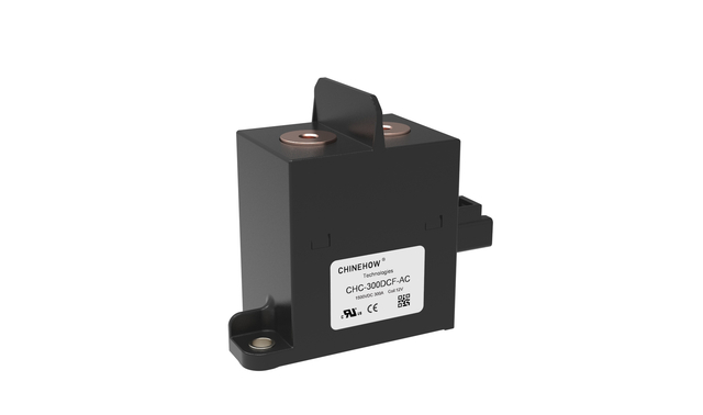
DC vs. AC Switching Realities: Unlike AC circuits, DC lacks a zero-crossing point, requiring active arc-extinguishing mechanisms to safely break the circuit.
Arc Suppression is Critical: Reliable high voltage DC contactors rely on magnetic blowouts and inert gas-filled hermetic seals to stretch, cool, and snap electrical arcs in milliseconds.
Sizing Requires Nuance: Specifying a contactor requires evaluating both continuous carry current and maximum fault breaking capacity to prevent micro-welding during inrush events.
Coil Efficiency Impacts System Design: Integrating coil economizers (via PWM or dual-coil designs) is essential to minimize holding power and reduce thermal stress in continuous-duty applications.
Protective Ecosystem Integration: Modern contactors do not operate in isolation; they must seamlessly interface with Battery Management Systems (BMS) and Electronic Control Units (ECU) for rapid fault isolation.
Table of Contents
An electromechanically operated, heavy-duty switch designed specifically to make, carry, and break high-voltage direct current circuits forms the backbone of modern power isolation. While traditionally spanning 400V to 800V, modern architectures increasingly push these devices to handle loads well above 1 kV. These contactors serve as the primary gatekeepers between massive energy reserves and the high-draw components that consume that energy. They withstand immense thermal shocks and mechanical impacts that would instantly vaporize lighter-duty switches.
Industry terminology often blurs the lines between different switching devices. While engineers sometimes use "high-voltage relay" and "high-voltage contactor" interchangeably in automotive contexts, contactors are specifically engineered for higher power loads. They feature specialized arc chutes and magnetic blowouts not found in standard relays. A relay typically handles control signals or low-power auxiliary circuits. A contactor manages the main power feed. The inclusion of heavy-duty magnetic blowouts, robust contact alloys, and advanced hermetic sealing firmly separates a true contactor from a standard relay.
The device acts as the primary safety disconnect and control switch. It isolates the power source, like a lithium-ion battery pack, from direct connections to high-load devices such as electric traction motors or grid-tied inverters. This isolation happens under both normal operational cycling and critical fault conditions. During normal operation, it allows power to flow efficiently with minimal resistance. During a crash, a short circuit, or a thermal event, it acts as the ultimate fail-safe, severing the connection to prevent catastrophic damage.
Field engineers rely on these devices to perform three primary functions within a power architecture:
Galvanic isolation to ensure technician safety during routine maintenance and system upgrades.
Emergency disconnect capabilities to sever power instantly when the control unit detects a dead short or thermal runaway.
Routine load switching to connect and disconnect inverters, motors, and charging circuits during standard daily operation.
The operation begins within the control circuit mechanics. Applying low-voltage DC power to the internal coil generates a concentrated magnetic field. This control voltage is typically 12V or 24V, completely isolated from the high-voltage side of the device. When current flows through the copper windings of the coil, it creates an electromagnet. The strength of this electromagnet is carefully calibrated to overcome the physical resistance of the internal return springs while operating within strict thermal limits.
The contactor's control circuit receives rapid actuation signals from a Battery Management System (BMS) or Electronic Control Unit (ECU). These intelligent control systems monitor voltage, current, and temperature across the entire power architecture. If the BMS detects an overcurrent event, a voltage drop indicating a short, or a temperature spike, it instantly cuts the low-voltage supply to the contactor coil. This integration ensures the mechanical disconnect happens in near real-time.
When energized, the magnetic force overcomes the resistance of the return spring, pulling the armature to close the main contacts and complete the high-voltage circuit. This physical movement must be swift and decisive to minimize the duration of any pre-strike arcing as the contacts approach each other. When the control signal drops, the magnetic field collapses instantly. The heavy-duty return springs then violently force the armature back to its resting position, ripping the main contacts apart to break the high-voltage circuit.
The standard actuation sequence follows a precise timeline:
The BMS verifies system safety and sends a 12V/24V signal to the coil terminals.
The coil generates a magnetic field, pulling the internal armature downward against the return spring.
The main contacts bridge the high-voltage gap, allowing current to flow to the load.
An internal economizer circuit activates, dropping the coil voltage to a lower holding level to prevent overheating.
Upon a fault detection, the BMS cuts the signal, the spring forces the contacts open, and the arc suppression mechanisms take over.
Breaking a DC circuit under load presents a severe physics challenge. As contacts separate, the current continues to flow through the air gap, ionizing the surrounding gas and creating a plasma arc that will not self-extinguish. Because direct current flows continuously in one direction, it lacks the natural zero-voltage crossing point found in alternating current. An AC arc extinguishes itself 100 or 120 times per second, making it relatively easy to interrupt. A DC arc will sustain itself as long as the voltage potential is high enough to bridge the physical gap between the separating contacts.
This plasma arc is incredibly destructive. It generates localized temperatures that rapidly melt copper and silver alloys. You must stretch the arc rapidly to increase its resistance, cool the plasma, and force the voltage required to sustain the arc higher than the system voltage. If the arc is not stretched and cooled within milliseconds, it will consume the internal components of the contactor. This leads to a catastrophic failure where the circuit remains live despite the mechanical separation of the contacts.
To combat the sustained plasma arc, engineers utilize Lorentz force applications by integrating permanent magnets positioned strategically around the contact gap. These magnets create a strong, continuous magnetic field perpendicular to the path of the electrical arc. When the contacts open and the arc forms, the electrical current flowing through the plasma interacts with this magnetic field. This interaction is a fundamental principle of electromagnetism, utilized here for critical safety.
The magnetic field interacts with the current in the arc, generating a force that physically blows the arc outward into an arc chute to snap and extinguish it safely. This directional arc control forces the plasma away from the contact surfaces, rapidly stretching it. As the arc stretches, its electrical resistance increases. Simultaneously, forcing the arc into the ceramic or resin walls of the arc chute cools the plasma. The combination of stretching and cooling raises the arc voltage until it exceeds the system voltage, causing the arc to collapse and the circuit to safely break.
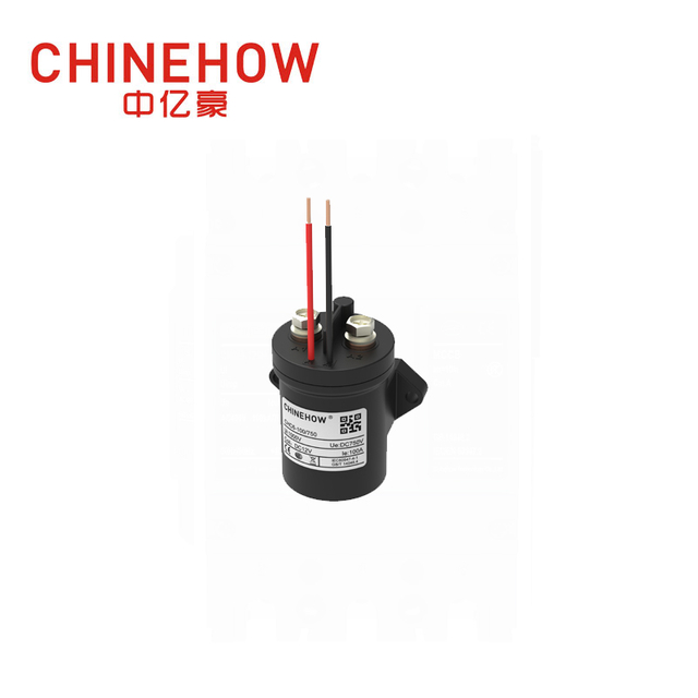
The physical points of connection bear the brunt of the electrical load and the destructive force of arcing. Material selection relies heavily on advanced silver alloys, most notably silver tin oxide (AgSnO2). Pure copper or pure silver would quickly weld together under the intense heat of a high-voltage break. Silver tin oxide provides exceptionally low contact resistance during normal operation while offering high resistance to material transfer and micro-welding during make-and-break cycles. The metal oxides dispersed within the silver matrix prevent the contacts from fusing, ensuring reliable separation even after thousands of cycles.
Contact geometry plays an equally vital role in arc suppression. Modern high-power devices utilize double-break contact designs, which create two simultaneous gaps when the armature drops away. This geometry effectively doubles the arc-extinguishing capability compared to single-break designs. By splitting the arc into two separate, smaller arcs in series, the total arc voltage is doubled. This makes it significantly easier for the magnetic blowouts and the surrounding gas to extinguish the plasma. This dual-gap approach is mandatory for handling voltages above 400V safely.
High-end high voltage DC contactor designs utilize epoxy or ceramic hermetic seals to protect internal components from moisture, dust, and oxidation. Environmental isolation is required because any contamination on the contact surfaces will drastically increase resistance, leading to heat generation and eventual failure. Ceramic seals offer superior thermal shock resistance and withstand the extreme internal pressures generated during a high-current fault interruption. Epoxy seals provide excellent protection for slightly lower power applications, ensuring a long operational lifespan in harsh automotive or industrial environments.
Inside this sealed chamber, the environment is carefully controlled. Filling the contact chamber with inert gases, such as hydrogen or specific nitrogen mixtures, drastically improves performance. These gases possess higher thermal conductivity and dielectric strength than standard atmospheric air. Hydrogen is highly effective at cooling the arc plasma rapidly. Displacing oxygen from the chamber prevents the oxidation of the silver alloy contacts, maintaining low contact resistance over the entire mechanical and electrical life of the device.
Evaluating the contactor's ability to carry a steady load without exceeding thermal limits requires looking at the continuous carry current. This rating dictates how much current the device can handle indefinitely without the internal components degrading from heat. It depends heavily on the cross-sectional area of the internal busbars, the quality of the contact surfaces, and the ambient operating temperature. If a system continuously draws 250 amps, the contactor must be rated for at least that amount under worst-case thermal conditions.
Assessing the absolute maximum fault current the contactor can safely interrupt once without catastrophic failure defines its maximum breaking current. This is often thousands of amps. If a dead short occurs in a battery system, the current will spike instantly. The contactor must open its contacts, stretch the massive arc, and extinguish it before the device explodes or welds shut. This rating is the ultimate measure of the device's safety capabilities.
Engineers must also factor in capacitive loads, like those found in large motor inverters, that draw massive initial currents. These inrush currents necessitate robust make-ratings. When the contactor closes, the initial surge can be ten times the continuous rating. If the contacts bounce even slightly during this surge, the resulting micro-arcs can weld the contacts together. Proper specification requires analyzing the exact load profile during the first few milliseconds of operation.
The shift toward 1000V+ systems requires evaluating the physical distance between conductive parts to prevent high-voltage tracking and flashovers. Creepage, which is the shortest path along an insulating surface, and clearance, the shortest path through the air, must be strictly maintained. As voltages increase, the risk of electricity jumping across gaps or tracking along contaminated surfaces rises. High-voltage designs must feature extended internal barriers and specialized insulating materials to meet international safety standards like IEC 60664 for high-voltage architectures.
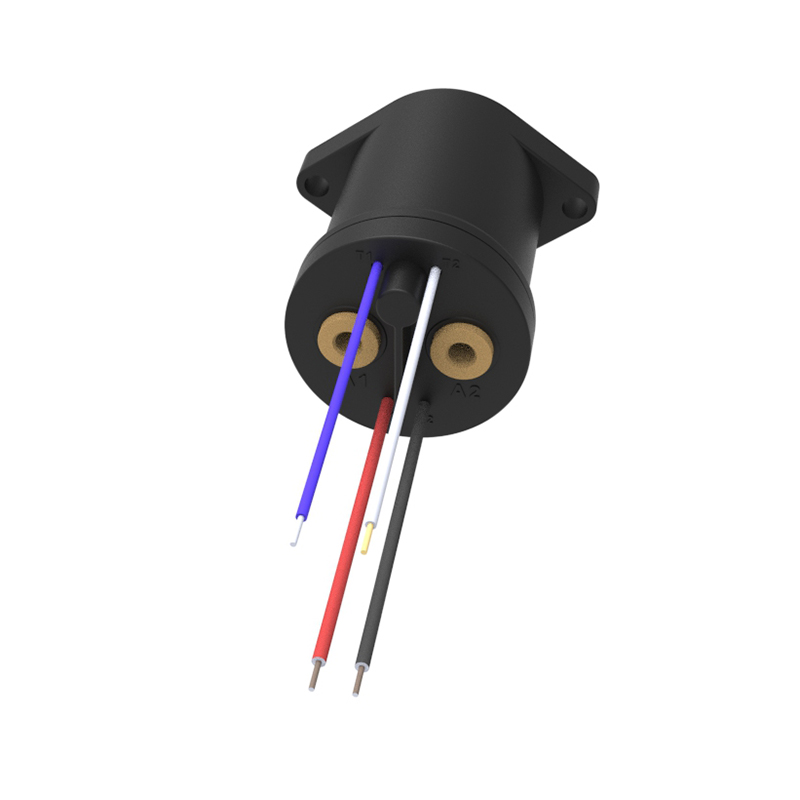
Continuously powering a coil to keep the contacts closed presents a significant thermal and efficiency trade-off. The holding power dilemma is a major factor in battery-powered applications. A large contactor might require 40 watts of power just to pull the armature in. If that 40 watts is maintained continuously, the coil will generate substantial heat, potentially degrading the surrounding insulation, and it will constantly drain the system's battery reserves.
Evaluating the necessity of coil economizers is a required step in system design. Economizers use Pulse Width Modulation (PWM) or dual-coil circuits to drop the holding current by up to 90% after initial actuation. A dual-coil design uses a high-power winding to forcefully close the contacts, then switches to a low-power winding simply to hold them in place. A PWM economizer rapidly pulses the voltage to the single coil, maintaining enough magnetic force to keep the contacts closed while drastically reducing overall power consumption and heat generation.
Understanding lifecycle degradation requires differentiating between mechanical life and electrical life. Mechanical life refers to no-load cycles, often numbering in the millions. This tests the physical durability of the springs, armature, and pivots without any electricity flowing through the main contacts. Electrical life refers to full-load breaks and is often limited to thousands or even hundreds of cycles. Breaking a high-voltage DC load physically erodes the contact material every single time due to the arcing.
Frequent high-current breaks, extreme ambient temperatures, and high altitudes accelerate contact wear and reduce electrical life. These derating factors must be calculated during the design phase. At high altitudes, the thinner air provides less cooling and lower dielectric strength, making arcs harder to extinguish. High ambient temperatures reduce the thermal headroom of the device, increasing the risk of overheating during continuous operation. You must consult derating curves provided by manufacturers to ensure the contactor will survive its intended environment.
Evaluation Criteria Summary
Specification Parameter | Definition | Field Application Impact |
|---|---|---|
Continuous Current Rating | Maximum steady-state current without thermal degradation. | Determines baseline operational capacity for normal loads. |
Maximum Breaking Capacity | Highest fault current the device can safely interrupt once. | Mandatory for short-circuit protection and system safety. |
Coil Holding Power | Energy required to keep the main contacts closed. | Impacts battery drain and internal thermal management. |
Electrical Life Cycle | Number of operations under full electrical load before failure. | Dictates maintenance schedules and long-term reliability. |
Dielectric Withstand Voltage | Maximum voltage the insulation can handle without breaking down. | Ensures safety against voltage spikes and system transients. |
The automotive sector drives massive innovation in high-voltage switching. Application realities include use in main battery disconnect units (BDU), pre-charge circuits, and direct connections to high-load traction motors. The BDU relies on these contactors to completely isolate the high-voltage battery pack from the rest of the vehicle when the car is turned off or when a fault is detected. Pre-charge contactors, which are smaller variants, are used to slowly charge the capacitors in the motor inverter before the main contactor closes, preventing massive inrush currents.
Specific requirements for EVs include high shock and vibration resistance, a compact footprint, and fail-safe operation during crash events. Vehicles experience constant physical stress from the road. The internal springs and armature must be robust enough to prevent accidental contact opening or closing during severe impacts. Space constraints within the battery pack demand contactors that offer maximum power density, handling massive currents within a very small physical envelope.
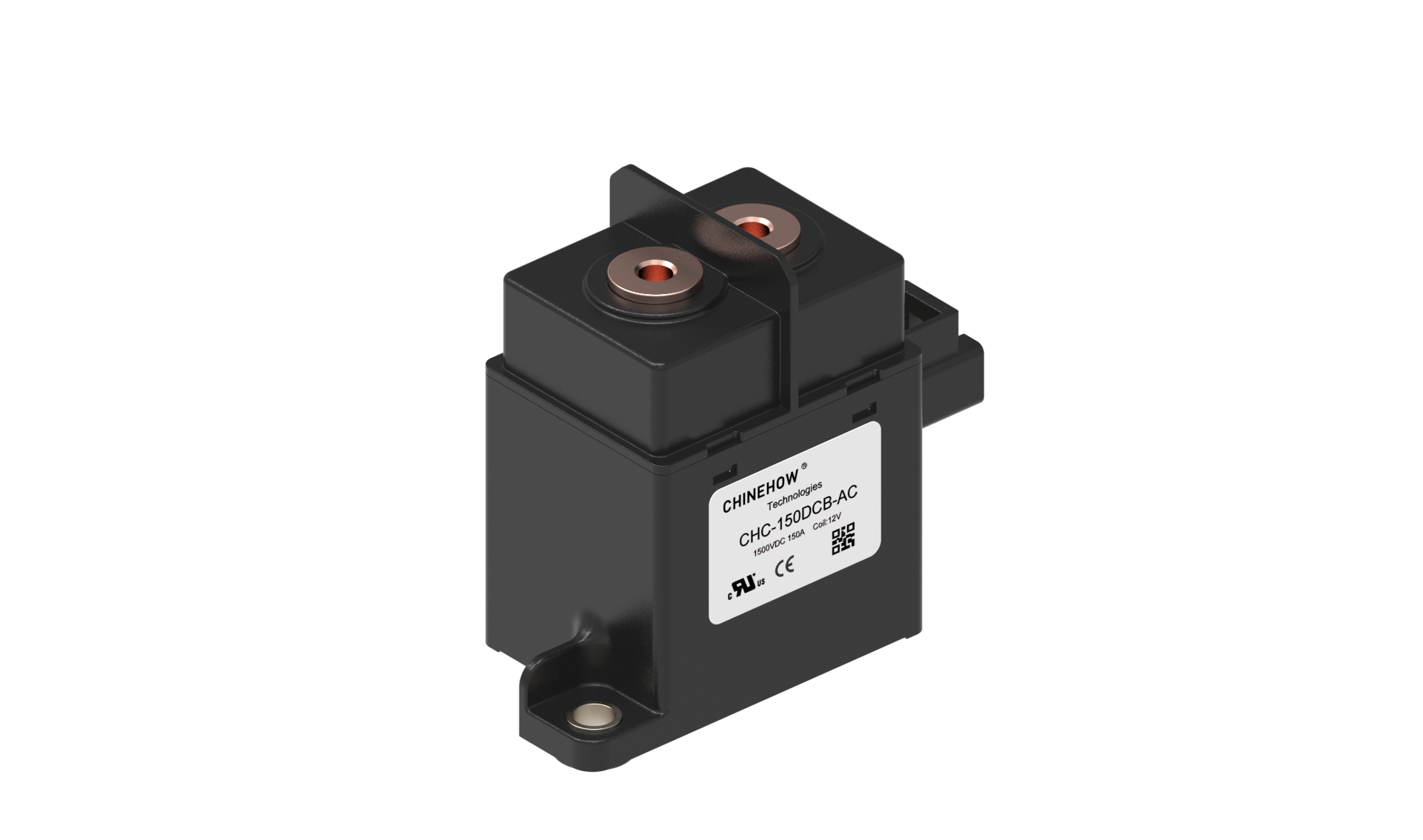
Grid-scale and residential battery storage isolation represent another massive deployment area. Application realities in ESS involve managing massive banks of lithium-ion or LiFePO4 batteries that store energy from solar arrays or the grid. These systems require contactors to isolate individual battery racks for maintenance or to disconnect the entire system from the grid during a power outage to prevent back-feeding.
Specific requirements for ESS include bidirectional current flow capabilities and extreme long-term holding reliability. Because batteries both charge and discharge, the current flows in two different directions depending on the operational state. The contactor must be capable of extinguishing arcs regardless of the current direction. ESS contactors may remain closed for months at a time, making coil economizers and low contact resistance absolutely mandatory to prevent long-term thermal degradation.
When integrating these devices into an ESS rack, field technicians follow a strict sequence:
Verify the maximum system voltage does not exceed the contactor's dielectric withstand rating.
Install pre-charge resistors in parallel with the main contactor to manage capacitive loads.
Mount the contactor in the correct orientation, ensuring gravity does not counteract the internal return springs.
Connect the low-voltage control lines to the BMS, verifying the PWM frequency matches the economizer specifications.
Torque the high-voltage busbar connections to the manufacturer's exact specifications to prevent localized heating.
The infrastructure supporting electric vehicles relies heavily on robust isolation technology. Application realities involve high-power transfer from grid-tied rectifiers directly to vehicle batteries. When a driver plugs in a DC fast charger, the contactors inside the dispensing unit close to initiate the flow of power. These systems operate at extremely high voltages, often up to 1000V, and push hundreds of amps to charge the vehicle rapidly.
Specific requirements for charging stations include high cycle rates, robust thermal management, and compliance with stringent public safety standards like UL and IEC. A busy charging station might see its contactors cycle dozens of times a day under heavy load. The devices must dissipate heat effectively to prevent continuous operation from degrading the internal components. Public safety mandates that these contactors fail safely, ensuring no high voltage is ever present at the charging cable when not actively charging a vehicle.
High inrush currents or dead short circuits can melt the contact surfaces, fusing them together and preventing the circuit from opening. This is the most severe risk in high-voltage DC design. If a contactor welds shut, the BMS loses its ability to isolate the battery pack. A thermal runaway event in the battery or a continuous short circuit will proceed unchecked, inevitably leading to a catastrophic fire or explosion.
To mitigate this risk, engineers must implement proper pre-charge circuits to equalize voltage before closing the main contactor. By routing initial power through a high-wattage resistor and a smaller pre-charge contactor, the system fills the downstream capacitors slowly. Once the voltage is equalized across the main contactor, it can close with zero inrush current. Designers must pair the contactor with fast-acting pyrotechnic or semiconductor fuses. If a dead short occurs, the fuse should blow before the contactor has a chance to weld, providing a redundant layer of short-circuit protection.
If a system fails to open, technicians perform a specific failure analysis:
Inspect the external housing for thermal discoloration or warping.
Measure the resistance across the main terminals while the coil is de-energized to confirm a welded state.
Check the low-voltage control circuit to ensure the BMS actually dropped the actuation signal.
Examine the system logs for unexpected inrush spikes that exceeded the make-rating of the device.
Installing a polarized contactor backward in a circuit presents a hidden but fatal danger. Because the permanent magnets used for arc blowouts have fixed magnetic fields, they are designed to push the arc in a specific direction based on the flow of current. If current flows in the wrong direction, the permanent magnets will blow the arc inward toward the coil and internal mechanisms rather than outward into the arc chute. This will instantly destroy the device and fail to break the circuit.
To mitigate this, engineers must specify non-polarized, bidirectional contactors for applications with regenerative braking or two-way power flow. Bidirectional designs utilize specialized magnet arrangements or dual arc chutes to safely extinguish the arc regardless of which way the current is flowing. For systems that only flow power in one direction, strict wiring protocols and physical keying must be enforced on the assembly line to ensure polarized units are never installed backward.
To ensure your high-voltage architecture remains safe and operational under extreme loads, follow these immediate next steps:
Map your exact load profile, including continuous current, peak inrush current, and maximum fault current, before selecting a device.
Verify whether your application requires bidirectional current flow and specify a non-polarized contactor if regenerative braking or charging is involved.
Implement a robust pre-charge circuit to protect the main contacts from micro-welding during initial startup.
Consult the manufacturer's derating curves to adjust your specifications based on the ambient temperature and altitude of your deployment environment.
Integrate a PWM or dual-coil economizer into your control circuit to minimize battery drain and reduce thermal stress on the coil.
For cutting-edge applications demanding uncompromised safety and durability, partnering with an established leader in electrical switching technology makes all the difference. Chinehow brings decades of advanced engineering experience and rigorous manufacturing standards to deliver premium high-voltage DC contactors and protection devices, helping industry innovators power next-generation energy and mobility systems safely.
A: AC contactors rely on the natural zero-voltage crossing of alternating current to extinguish electrical arcs. DC contactors handle continuous current without a zero-crossing, requiring specialized magnetic blowouts, arc chutes, and hermetic sealing to physically stretch and cool the plasma arc to break the circuit safely.
A: While a DC contactor can technically interrupt an AC load, it is generally over-engineered and inefficient for that purpose. Conversely, an AC contactor must never be used in a high-voltage DC circuit, as it lacks the necessary magnetic arc suppression and will fail catastrophically under load.
A: Direct current creates a sustained plasma arc when contacts separate under load. Magnetic blowouts use permanent magnets to generate a Lorentz force, which physically pushes the electrical arc away from the contacts and into an arc chute, stretching and cooling it until it extinguishes.
A: Contact welding occurs when massive inrush currents or short circuits generate enough heat to melt the silver alloy contacts, fusing them together. Failure can also result from continuous operation above thermal limits, loss of hermetic seal integrity, or installing a polarized contactor backward.
A: A pre-charge contactor is a smaller relay used in series with a resistor to slowly charge downstream capacitors. This equalizes the voltage across the main contactor before it closes, preventing massive inrush currents that would otherwise weld the main contacts.
A: A coil economizer reduces the power required to keep the contactor closed. It uses Pulse Width Modulation (PWM) or a dual-coil circuit to deliver high power for the initial mechanical pull-in, then drops the current significantly to maintain the magnetic hold, reducing heat and battery drain.


