
Views: 0 Author: Site Editor Publish Time: 2026-08-20 Origin: Site


High-voltage DC systems are scaling rapidly. We see this across utility solar arrays, electric vehicle drivetrains, and residential battery energy storage setups. With this growth comes a strict demand for precise electrical control and heavy-duty fault protection. System designers and field engineers often run into component overlap confusion. Misapplying a control device for a protection role leads to melted panels, thermal runaway, and severe code violations. You cannot swap these parts based on voltage ratings alone. Understanding the exact mechanical architectures, internal working principles, and operational lifespans dictates whether a system runs safely or fails catastrophically. This guide breaks down the exact differences between these components. We will look at how to integrate them properly into modern DC power systems to ensure compliance and field reliability. Choosing a DC contactor vs DC circuit breaker comes down to matching the right mechanical tool to the specific electrical hazard.
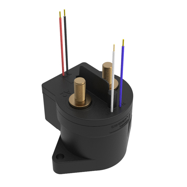
Distinct Primary Roles: DC contactors are designed for high-frequency, normal-load switching (automated control), whereas DC circuit breakers are engineered to interrupt abnormal overcurrents and short circuits (automatic protection).
Mechanical Lifespan: Contactors support millions of operational cycles; circuit breakers are designed for infrequent tripping and have a highly limited lifespan under fault-clearing conditions.
Arc Suppression Realities: DC circuits lack a "zero-crossing" point, making arc extinguishing inherently difficult. Both components use specialized magnetic blowouts and wide contact gaps, but they deploy them for entirely different operational thresholds.
Power Consumption: Contactors typically require continuous power to keep their coils energized (unless latching), whereas circuit breakers remain mechanically latched without consuming power.
System Synergy: In both industrial and residential applications, these components are rarely mutually exclusive. Optimal system architecture typically pairs a contactor for operational cycling with a circuit breaker for ultimate fault isolation.
Table of Contents
A DC contactor is an electrically controlled switch. We use it to open and close a power circuit remotely or automatically. Manual switches require a human operator to physically move a lever. Contactors rely on low-voltage control signals to manage high-voltage, high-current loads. You find them in automated systems where power cycles on and off repeatedly. For example, a battery management system uses a contactor to disconnect the battery bank from the inverter when the state of charge drops too low.
The internal mechanism relies on electromagnetism. Applying a control voltage to the internal coil generates a magnetic field. This field pulls an armature downward. The movement forces the main heavy-duty contacts to close, completing the high-power circuit. Removing the control voltage allows a mechanical spring to push the contacts apart, breaking the circuit. Control coils come in various voltages, typically 12V, 24V, or 48V DC, allowing them to interface directly with programmable logic controllers or microcontrollers.
We use contactors to make and break normal load currents reliably. They handle the continuous rated current of a system. They safely interrupt standard operational loads. They do not clear massive short-circuit faults. Subjecting a contactor to a dead short generates extreme heat. This heat melts the silver-alloy contact pads and welds them together. The device becomes permanently closed, creating a massive safety hazard that requires immediate system shutdown.
A DC circuit breaker is an automatically operated electrical safety device. You can manually toggle it on or off, but its main job is monitoring the circuit and severing the connection when it detects dangerous electrical anomalies. It acts as the ultimate fail-safe in your power architecture. We install them to protect the wiring infrastructure from melting and starting fires.
The internal trip mechanisms use a dual-layered approach. First, a bimetallic strip provides delayed thermal overload protection. Current flowing through the breaker generates heat. If the current exceeds the rated limit for a prolonged period, the bimetallic strip bends. This bending triggers the mechanical latch and opens the circuit. Second, a magnetic coil provides instantaneous short-circuit tripping. A massive fault current spikes through the system. The magnetic field instantly pulls the trip latch. The circuit breaks in milliseconds before wires melt or batteries catch fire.
We install breakers to detect fault conditions and physically break the circuit. This prevents equipment damage and fire hazards. It is a protection device first. You should not use it as a daily on/off switch for your equipment.
System design also involves DC isolators. You must distinguish isolators from contactors and breakers. Isolators are strictly manual disconnect switches. They provide a visible, physical break in the circuit for safe maintenance and servicing. They lack remote automation capabilities. They completely lack automatic fault-tripping mechanisms. Most isolators are non-load break devices. You must power down the system before turning the isolator handle. Turning it under load draws a dangerous electrical arc that can destroy the switch and injure the operator.
Component Architecture and Performance Comparison
Feature | Contactor Unit | Breaker Unit |
|---|---|---|
Primary Function | Automated operational control | Automatic fault protection |
Actuation Method | Electromagnetic coil (remote) | Thermal-magnetic trip (automatic) / Manual toggle |
Mechanical Endurance | 100,000 to millions of cycles | 1,000 to 10,000 cycles |
Fault Clearing Ability | None (contacts will weld) | High (rated in kA for short circuits) |
Power Consumption | Requires continuous holding current | Zero power consumption (mechanically latched) |
Arc Suppression Method | Magnetic blowouts | Heavy-duty arc chutes and magnetic blowouts |
Typical Installation Location | Downstream, near the load | Upstream, near the power source |
A contactor succeeds by operating seamlessly thousands of times a day. It connects solar arrays to charge controllers at dawn. It disconnects battery banks when they reach full capacity. It pulses power to electric motors. A breaker succeeds by acting as the fail-safe during a rare anomaly. It sits quietly for years. It conducts current without interruption. It only springs into action when a wrench falls across busbars or wire insulation fails.
Mechanical and electrical endurance ratings highlight the stark contrast between these devices. Contactors carry ratings for high mechanical endurance. They support 100,000 to millions of electrical cycles. Manufacturers harden the internal springs, armatures, and contact pads. These parts withstand the physical shock of constant opening and closing. You can cycle a contactor every minute of the day without degrading its mechanical integrity.
Circuit breakers degrade rapidly if used as standard on/off switches. You can manually toggle a breaker, but the internal latching mechanisms are complex and prone to wear. A breaker has a highly limited fault-clearing lifespan. Depending on the severity of the short circuit, a breaker may only survive a few dozen fault interruptions. After that, the internal arc chutes and contact surfaces degrade too much to function safely. You must replace the entire unit after it clears a severe short circuit.
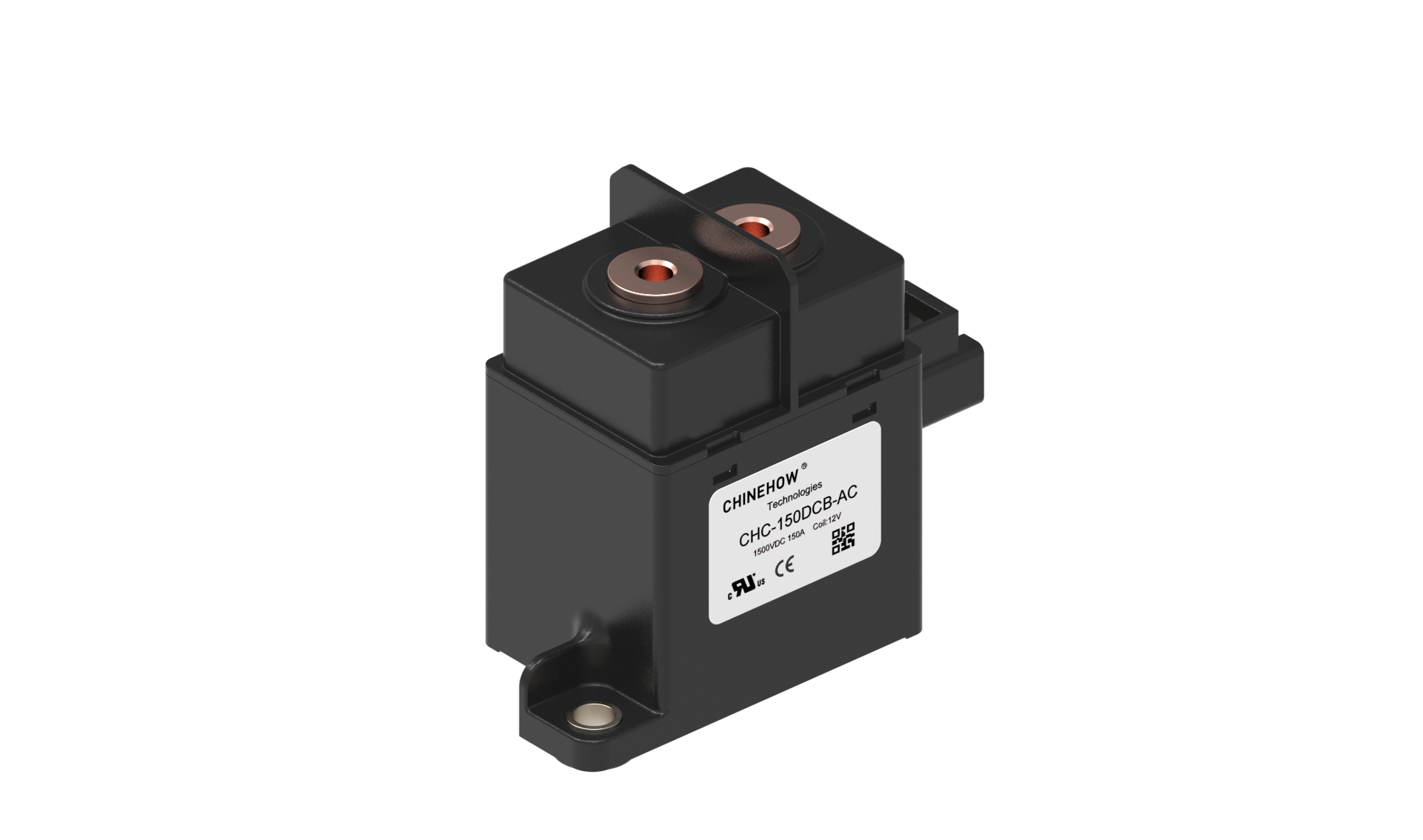
Arc suppression requires understanding the physics of continuous DC voltage. Alternating current naturally crosses zero volts 100 or 120 times per second. When an AC switch opens, the arc naturally extinguishes at that zero-crossing point. Direct current has no zero-crossing. It provides continuous, unrelenting voltage. Pulling two contacts apart in a DC circuit ionizes the air. The current jumps the gap. It sustains a plasma arc that reaches thousands of degrees.
DC breakers utilize wider contact gaps and heavy-duty arc chutes to handle this. When a breaker trips under a massive fault, the magnetic forces push the arc into a series of parallel metal plates. These plates physically stretch, slice, and cool the plasma arc. The voltage can no longer sustain it, and the fault extinguishes. This mechanism is bulky but mandatory for handling massive fault currents safely.
Contactors utilize magnetic blowouts to stretch and extinguish arcs during normal load switching. Permanent magnets sit near the contact pads. As the contacts open and an arc forms, the magnetic field interacts with the arc's electromagnetic field based on the Lorentz force principle. This forcefully blows the arc outward away from the contacts until it snaps. This works highly effectively for standard operational currents. It fails completely against dead-short fault currents.
Standard contactors require continuous electrical power to the coil to stay closed. This generates heat. It causes a minor, constant parasitic power loss in your system. Modern contactors use economizer circuits or pulse-width modulation. An economizer circuit might pull 3 amps at 12V to initially close the heavy contacts. Once closed, the circuit drops the holding current to 0.2 amps. This prevents the coil from burning out during continuous operation and saves battery power. Latching contactors also exist. They use a pulse to close and a pulse to open, requiring zero continuous power. Standard normally-open contactors require constant power.
Circuit breakers utilize mechanical latches. Once you manually close the breaker, it remains locked in the closed position mechanically. It consumes zero power while allowing continuous, uninterrupted power flow. Breakers are highly efficient for long-term power transmission where automated switching is not required.
Size trade-offs dictate panel design. Contactors are generally more compact. They do not need complex thermal-magnetic trip units. They lack massive arc chutes designed for 50kA faults. You can integrate them tightly into control panels, motor drive enclosures, and battery management systems. They mount easily on flat backplates.
Circuit breakers are inherently bulkier. The physical space required for the bimetallic strip, the magnetic solenoid, the manual toggle mechanism, and the extensive arc-extinguishing chambers adds up. Breakers take up significantly more room on a DIN rail or mounting backplate. High-amperage molded case circuit breakers require substantial clearance around the terminals to prevent arc flashover to the metal enclosure.
Evaluate continuous current versus peak inrush current. Capacitive loads, like inverters, draw a massive spike of current for a few milliseconds when first connected. The capacitors charge rapidly. A contactor must handle this inrush without welding. Otherwise, you must install a pre-charge circuit. A breaker must have a magnetic trip curve that ignores this brief inrush but still trips during a genuine short circuit.
Match the component's DC voltage rating to the maximum system voltage. A 48V DC breaker will violently fail if installed in a 400V DC system. The internal gaps are not wide enough to stop a 400V arc. This leads to immediate arc flashover and fire. Calculate the maximum open-circuit voltage of your solar array or battery bank. Account for cold weather voltage spikes. Select components rated well above that number.
The Short Circuit Current Rating defines the maximum fault current a device can safely interrupt without exploding. Battery banks, particularly lithium iron phosphate chemistries, have incredibly low internal resistance. In a dead short, a standard residential battery bank delivers 10,000 amps or more in an instant. The wiring acts as a dead short, and the battery dumps all available energy into that short.
A contactor will weld its contacts shut during a dead short. It lacks the mechanical force and arc chutes to break that level of current. A properly sized DC circuit breaker clears high kA faults safely. Calculate the prospective short-circuit current of your power sources. Ensure your breaker's kA rating exceeds it. If your battery bank can deliver 15kA into a short, your breaker must have an interruption rating of at least 20kA.

A DIY off-grid solar setup or residential energy storage system requires smaller DIN-rail mounted DC breakers and compact contactors. These are manageable, easy to wire, and fit into standard consumer units. You torque the terminals with standard hand tools.
Utility-scale solar installations and industrial microgrids require molded case circuit breakers and heavy-duty industrial contactors. These industrial components feature adjustable trip settings, remote monitoring capabilities, and massive busbar connections. They handle hundreds of amps continuously. Installation requires heavy-duty crimpers, specialized torque wrenches, and strict adherence to industrial safety protocols.
Never install uncertified electrical components. Verify UL and IEC standards specific to DC applications. For circuit breakers, look for UL 489 for molded-case circuit breakers or UL 1077 for supplementary protectors. UL 489 is mandatory for main branch protection. For contactors, look for UL 60947-4-1. In international markets, IEC 60947-2 applies to breakers and IEC 60947-4-1 applies to contactors.
Regulatory and insurance implications of using non-certified components are severe. Inspectors will fail the project if components lack proper listings. If an uncertified component causes a fire, insurance providers routinely deny the claim. Always check the manufacturer datasheet to confirm the exact certification numbers.
Specify a DC contactor when your system requires automated, high-frequency switching. We use them heavily in the field for specific tasks.
Electric Vehicle drivetrains and charging stations. The main battery must connect and disconnect from the motor controller based on ignition status and safety interlocks.
Battery Management Systems. They connect or disconnect battery banks under normal load. If a cell reaches over-voltage, the system drops the control signal to the contactor, isolating the battery safely.
Automated industrial processes. They handle remote switching of high-power DC heating elements or heavy DC motors on factory floors.
Solar charge controller outputs. They manage automated load shedding when battery voltage drops below a specific threshold.
Specify a DC circuit breaker when your system requires robust overcurrent protection and manual isolation.
Solar PV combiner boxes. They protect the wiring from short circuits and allow technicians to isolate the arrays safely before maintenance.
Main battery disconnects for energy storage systems. They provide a fail-safe against catastrophic battery shorts.
Main inverter inputs. They protect the heavy gauge wiring running between the DC busbar and the inverter terminals.
Any node in a system requiring manual isolation combined with automatic fault protection.
Robust system design rarely treats these components as mutually exclusive. The standard design framework places the DC circuit breaker upstream, closest to the power source. This provides immediate short-circuit protection and a manual isolation point for the entire branch. The DC contactor sits downstream, handling the automated, high-frequency load control.
Selecting the right combination prevents catastrophic failures while allowing smart system automation. The breaker acts as the heavy armor, standing guard against rare but devastating faults. The contactor acts as the agile operator, managing the daily workflow of power distribution. You wire the breaker to protect the wire, and you wire the contactor to control the load.
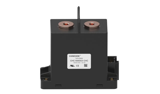
A frequent and highly dangerous error in amateur builds is substituting AC circuit breakers for DC applications. AC breakers are cheaper and more readily available. Builders assume a 250V AC breaker can handle 48V DC. This is a fatal misconception.
AC breakers have smaller contact gaps. They rely on the AC sine wave crossing zero volts to extinguish the arc. They lack the robust magnetic blowouts and heavy arc chutes required for DC. If an AC breaker trips under a DC load, it fails to extinguish the continuous DC arc. The plasma melts the plastic housing, welds the contacts, and inevitably leads to a severe electrical fire. Always use components explicitly rated for DC voltage.
Contact welding occurs when the heat generated during closing or opening melts the silver-alloy contact pads. They fuse together. Primary causes include excessive inrush currents from charging capacitors, switching highly inductive loads without snubber circuits, or voltage dips causing the internal coil to chatter.
Mitigate this by implementing pre-charge circuits. A 48V inverter has massive input capacitors. Closing a contactor directly into uncharged capacitors acts like a dead short for a few milliseconds. The inrush current can exceed 1000 amps. A pre-charge circuit uses a 50-ohm power resistor and a small relay to trickle charge the capacitors for 3 seconds before the main contactor closes. Ensure proper coil voltage regulation so the contactor receives a solid, unwavering control signal. Specify contactors with high make/break capacities that exceed your system's maximum operational parameters.
Nuisance tripping occurs when a breaker opens the circuit during normal operation. This causes frustrating power outages. Improper thermal sizing for ambient panel temperatures or magnetic trip settings that are too sensitive for system inrush currents usually cause this.
Breakers are thermal devices. Installing a breaker in a hot enclosure sitting in direct sunlight pre-heats the bimetallic strip. It trips at a much lower current than its rating. Mitigation requires proper derating based on manufacturer temperature curves. Careful trip-curve selection is vital. A Curve B breaker trips quickly and suits resistive loads. A Curve C or Curve D breaker allows brief surges without tripping. You need these for motor loads and inverters.
You must also pay attention to breaker polarity. Polarized breakers have a specific line and load direction due to the placement of the magnetic blowouts. Wiring them backward means the arc blows away from the arc chute, destroying the breaker. Non-polarized breakers handle bi-directional current flow. You must use non-polarized breakers for battery systems that both charge and discharge.
Audit your system's single-line diagram to ensure every power source has dedicated overcurrent protection via a properly sized DC breaker.
Calculate your maximum short-circuit current to verify your breakers have an adequate kA interruption rating.
Determine your required switching frequency and evaluate your power consumption constraints to select the right contactor coil type.
Consult manufacturer datasheets to confirm all selected components carry the appropriate UL or IEC certifications for high-voltage DC use.
To guarantee the highest level of safety and performance for your high-voltage DC projects, partner with industry specialists like Chinehow. Leveraging advanced manufacturing technology and extensive engineering expertise, Chinehow delivers top-tier electrical control and protection components designed to perform flawlessly in demanding modern power systems.
A: No. Contactors cannot interrupt short-circuit faults and lack thermal-magnetic trip mechanisms. Using one in place of a breaker removes overcurrent protection and creates a severe fire hazard during a fault event.
A: A DC isolator is a manual switch used to safely disconnect a circuit for maintenance. It offers no automatic fault tripping. A DC circuit breaker automatically trips to cut off abnormal current while also allowing manual disconnection.
A: DC voltage is continuous and does not cross zero volts. Wider gaps and specialized arc chutes are required to physically stretch, cool, and break the continuous electrical arc that forms when contacts separate under load.
A: Contactors are rated for millions of mechanical cycles and hundreds of thousands of electrical cycles under normal loads. Circuit breakers sit idle and require immediate replacement after clearing a severe short-circuit fault.
A: Absolutely not. AC breakers lack the necessary arc-extinguishing capabilities, magnetic blowouts, and contact spacing for DC currents. Using an AC breaker in a DC application will result in the breaker catching fire during a fault.


