
Views: 0 Author: Site Editor Publish Time: 2026-07-29 Origin: Site


High inrush currents and fluctuating ambient temperatures frequently cause nuisance tripping or catastrophic protection failures in critical electrical systems. Specifying engineers must balance the need to ride through temporary transients, such as motor starts or transformer energization, with the mandate to instantly interrupt genuine fault currents. This challenge is compounded in environments where traditional thermal breakers derate unpredictably, leaving systems vulnerable to either premature shutdowns or sustained thermal damage.
Analyzing and specifying the correct hydraulic magnetic circuit breaker trip curve provides a temperature-stable, highly customizable protection profile. By understanding the mechanics of fluid-damped magnetic interruption, you can precisely match breaker response times to load characteristics. This guide breaks down how to evaluate, select, and implement the exact trip curve required for your specific load characteristics, ensuring reliable operation across diverse operating conditions.
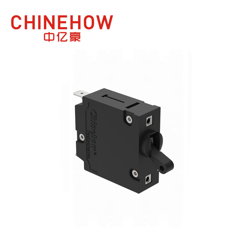
Temperature Independence: Unlike thermal-magnetic breakers, hydraulic magnetic trip curves remain stable across extreme temperature variations, eliminating the need for complex derating calculations.
Customizable Time Delays: The integration of a fluid-filled dashpot allows engineers to specify exact time-delay curves (fast, medium, long) to match specific inrush profiles without oversizing the breaker.
Must-Hold vs. Must-Trip Boundaries: Understanding the exact tolerances—typically a 100% "must-hold" and 125% or 135% "must-trip" threshold—is critical for precise system coordination.
Orientation & Vibration Sensitivity: Because the internal mechanism relies on a spring, a movable iron core, and physical fluid displacement, mounting orientation and mechanical shock can shift the trip curve.
Application Specificity: Selecting the right curve requires precise mapping of the load’s transient duration, continuous current draw, and the circuit's operating frequency (DC, 50/60Hz, or 400Hz).
Table of Contents
To accurately protect a circuit, the breaker's response must perfectly mirror the load's safe operating limits. Understanding the mechanics behind the curve is the first step in evaluation. The physical construction of the breaker directly dictates its graphical performance, translating magnetic forces and fluid dynamics into reliable electrical protection. When you look at the internal components, you see a system designed for mechanical precision rather than thermal reaction.
The core of this technology relies on a series-connected solenoid coil. As load current passes through this coil, it generates magnetic flux proportional to the current magnitude. Under normal operating conditions, this magnetic force is insufficient to actuate the tripping mechanism. The system remains stable, allowing continuous power flow to the connected load.
Inside the coil sits a hermetically sealed, non-magnetic tube called a dashpot, filled with a specialized silicone fluid. A spring-loaded iron core rests inside this fluid. When an overload occurs, the magnetic flux pulls the iron core toward the pole piece. The movement of this core is intentionally slowed by the displacement of the silicone fluid, creating the inverse time-delay characteristic. The viscosity index of the silicone fluid dictates the damping behavior and physical delay timing. Thicker fluids create longer delays, while thinner fluids allow faster movement.
The sequence of operation during an overload follows these specific mechanical steps:
Current exceeds the rated threshold, increasing the magnetic flux in the coil.
The magnetic force overcomes the resting spring tension holding the iron core.
The core begins moving through the silicone fluid, with speed dictated by fluid viscosity and overload magnitude.
Once the core reaches the pole piece, magnetic reluctance drops significantly.
The sudden increase in magnetic force actuates the armature, unlatching the breaker contacts.
If a massive short-circuit fault occurs, the magnetic force becomes so severe that it overcomes the spring instantly. This generates enough flux to actuate the armature without waiting for the iron core to move through the fluid, bypassing the dashpot entirely. This defines the instantaneous trip threshold, providing immediate protection against catastrophic faults.

When analyzing a trip curve datasheet, engineers look at a logarithmic graph mapping time against current. You must understand how to read these charts to specify the correct component for your panel.
The X-axis represents current, expressed as a percentage or multiple of the breaker's rated current (e.g., 100%, 125%, 200%, 1000%).
The Y-axis represents trip time in seconds, typically on a logarithmic scale spanning from 0.001 seconds to 1,000 seconds.
Because mechanical manufacturing involves slight physical variations, breakers do not trip at a single mathematical line. Instead, they operate within a tolerance band. This band is the area between the minimum and maximum trip time curves on the graph. A properly specified breaker will trip somewhere within this shaded region for any given overcurrent. You must design your system assuming the breaker could trip at the fastest edge of the band or hold until the slowest edge.
Two boundaries define this operation. The "must-hold" limit is typically set at 100% of the rated current, meaning the breaker will carry its full rated load indefinitely without tripping. The "must-trip" limit, usually set at 125% or 135% of the rated current, is the threshold where the breaker is guaranteed to trip within a specified time window. Operating between these two limits is the gray area where tripping may or may not occur depending on exact manufacturing tolerances and minor environmental factors.
Comparing protection technologies helps justify the specification of hydraulic magnetic breakers over alternative options. The primary differentiator is how the internal mechanisms react to ambient heat and cold. When you design panels for outdoor or unconditioned spaces, thermal management becomes a massive engineering headache.
Thermal-magnetic breakers rely on bimetallic strips that warp based on heat generated by the current passing through them. Because they depend on heat to operate, they are highly susceptible to ambient temperature changes. If a thermal breaker is installed in a hot environment, the ambient heat pre-warps the bimetallic strip. This causes the trip curve to shift to the left, meaning the breaker will trip early, often well below its rated current. You end up with nuisance trips on hot summer days even when the load is operating normally.
Conversely, in freezing environments, the strip requires more current-generated heat to warp, shifting the curve to the right. The breaker might fail to protect the circuit during a genuine overload because the ambient cold keeps the bimetal strip from bending at the intended current threshold.
Hydraulic magnetic breakers offer precise, stable trip points regardless of ambient heat. Because they rely on magnetic flux rather than thermal expansion, their current-carrying capacity remains constant. The trade-off is that these precision mechanisms typically carry a higher initial component cost compared to mass-produced thermal units. However, the operational reliability often offsets the upfront expense.
Feature | Thermal-Magnetic Breaker | Hydraulic Magnetic Breaker |
|---|---|---|
Sensing Mechanism | Bimetallic strip (heat) | Solenoid coil (magnetic flux) |
Temperature Sensitivity | High (requires derating) | None (stable from -40°C to +85°C) |
Nuisance Tripping Risk in Heat | High | Low |
Time Delay Customization | Limited | Highly customizable via fluid viscosity |
This temperature independence is vital for outdoor telecom enclosures, marine engine rooms, solar inverters, and high-density industrial control panels. In these applications, temperatures fluctuate wildly from day to night and season to season. A hydraulic magnetic breaker ensures that the "must-hold" rating remains at exactly 100% of the rated current from -40°C to +85°C, providing consistent protection without requiring engineers to oversize the breaker to compensate for summer heat.
When you oversize a thermal breaker to prevent summer nuisance tripping, you inherently compromise the protection level during the winter. Hydraulic magnetic technology eliminates this dangerous compromise entirely.
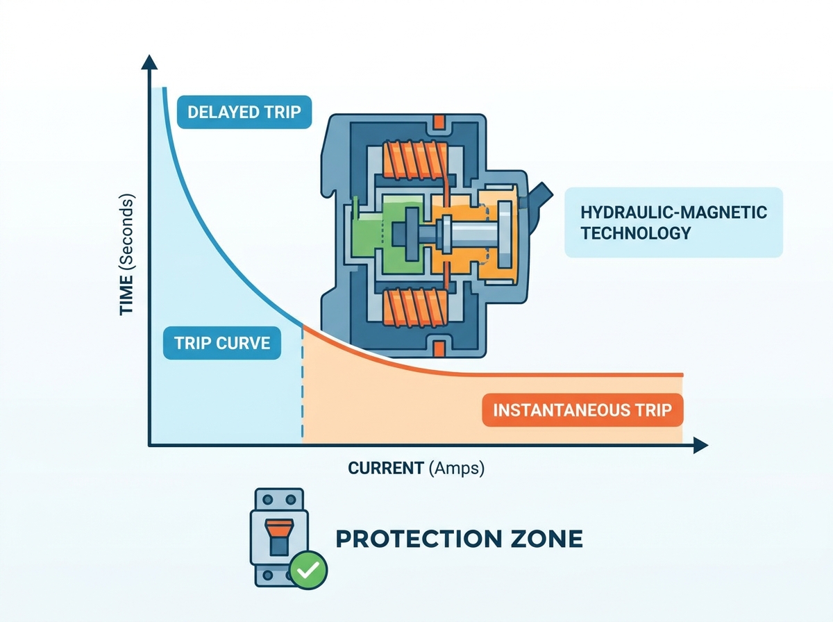
Manufacturers offer various standard industry trip curves, allowing engineers to map the breaker's response directly to specific load profiles. Selecting the correct delay prevents nuisance tripping while maintaining rigorous protection. You cannot use a one-size-fits-all approach when dealing with diverse electrical loads.
Fast trip curves feature little to no time delay, tripping almost immediately (often in milliseconds) upon sensing an overcurrent. These are best suited for sensitive electronic equipment, semiconductor protection, medical instruments, and purely resistive loads with zero inrush current. In these applications, any sustained overcurrent can cause immediate component failure. The fluid in the dashpot is extremely thin, or the mechanical linkage is designed to bypass the delay almost entirely.
Medium curves provide a moderate delay, allowing for minor, short-duration transients to pass without interrupting power. They are the standard choice for general lighting, mixed control loops, office equipment, and standard power distribution where minor inrush is expected but heavy motor starting is not present. This curve mimics the general response of standard wall outlets and basic commercial distribution panels.
Long trip curves introduce a significant time delay. This allows heavy, sustained transients to pass without tripping the breaker. They are essential for motors, solenoids, transformers, and industrial machinery with high starting currents that take several seconds to reach steady-state operation. The dashpot uses a high-viscosity silicone fluid that forces the iron core to move slowly, buying the equipment time to spin up and drop its current draw back to normal levels.
Modern high-efficiency equipment often generates massive, half-cycle spikes upon startup. High inrush curves feature a specialized inertial wheel or a modified dashpot designed to ignore these massive spikes—sometimes up to 30 times the rated current—while maintaining a standard overload curve for continuous protection. These are best for high-efficiency AC motors, switching power supplies, and large capacitive loads. The mechanical damper absorbs the initial kinetic energy of the magnetic spike without moving the trip latch.
For engineers transitioning legacy system specifications, it is helpful to map hydraulic-magnetic delay curves to traditional IEC thermal-magnetic curve designations. This ensures continuity when upgrading older panels.
Hydraulic-Magnetic Curve | Typical IEC Equivalent | Primary Application |
|---|---|---|
Fast Delay | Type B / Type Z | Sensitive electronics, resistive loads |
Medium Delay | Type C | General distribution, lighting, small motors |
Long Delay | Type D / Type K | Transformers, heavy industrial motors |
High Inrush (Inertial) | Specialized Motor Protection | Switching power supplies, high-efficiency AC motors |
Selecting the exact curve requires an engineering framework based on empirical load data. Guessing the inrush profile often leads to operational failures. You must measure the actual physical behavior of the circuit under load.

To accurately protect a circuit, you must capture and plot the load's transient profile using an oscilloscope. This involves measuring the peak amplitude, the inrush decay envelope, and the steady-state duration.
Connect a current probe to the oscilloscope and clamp it around the primary load conductor.
Trigger the oscilloscope to capture the exact moment of equipment startup.
Record the peak current spike and measure the time it takes for the current to settle to its continuous rating.
Plot these data points directly onto the manufacturer's trip curve datasheet.
Once this data is captured, overlay the load profile onto the breaker's datasheet graph. Ensure the inrush current curve sits comfortably below the minimum trip boundary of the tolerance band. If the load profile crosses into the shaded tolerance area, nuisance tripping is likely, and you must select a curve with a longer delay or an inertial dampener.
Selective coordination ensures that a fault is isolated locally by the nearest downstream breaker, avoiding cascading blackouts across the entire facility. You must ensure the selected trip curve coordinates with main breakers and downstream fuses. Analyze the intersection points of multiple trip curves on a single coordination study graph to ensure there are no overlapping tolerances between the primary and secondary protection devices. The downstream breaker must clear the fault before the upstream breaker even begins to unlatch.
The magnetic flux generated by the internal coil behaves differently depending on the power source. A breaker calibrated for 60Hz will have a different trip curve if applied to a DC circuit due to differing magnetic flux properties and inductance. Evaluating how the curve shifts based on DC, AC 50/60Hz, or AC 400Hz is necessary for proper specification. While some manufacturers offer dual-frequency calibrated curves, these often come with wider tolerance bands, reducing the precision of the protection.
Physical and environmental realities can compromise the intended protection profile. Identifying these risks early prevents field failures and costly redesigns.
The internal iron core's movement is affected by gravity. Mounting a breaker horizontally when it was calibrated for vertical mounting can shift the trip curve, typically accelerating or delaying the trip by 10% to 20%. The weight of the core either fights the magnetic pull or assists it, depending on the orientation. Always specify the mounting plane during procurement or apply the manufacturer's orientation derating factors to adjust your calculations.
High-vibration environments, such as mobile equipment, marine vessels, or railway systems, can cause mechanical displacement within the dashpot or armature. This leads to premature tripping along the curve. The physical shaking can bounce the latch mechanism open even if the magnetic flux is below the trip threshold. Select breakers with vibration-resistant dampening systems or specify mounting positions designed to counter dominant shock vectors.
While the ultimate trip point remains temperature-stable, extreme cold increases the viscosity of the silicone fluid in the dashpot. At -40°C, the thicker fluid extends the time delay during an overload. The breaker will still trip at the correct current level, but it will take slightly longer to do so. Review the manufacturer's low-temperature time-delay variance data for applications in arctic or high-altitude environments to ensure the extended delay does not damage downstream wiring.
Using a standard long-delay curve for a modern high-efficiency switching power supply often results in nuisance tripping on startup due to sub-millisecond capacitive surges. Specify breakers with dedicated transient-suppression mechanisms for modern capacitive loads rather than relying on standard delay curves. An inertial wheel mechanism physically blocks the armature from moving during microsecond spikes, providing superior protection without requiring a massive time delay for normal overloads.
Selecting the correct hydraulic magnetic circuit breaker trip curve requires more than matching the breaker’s rated current to the continuous load. Engineers must evaluate startup inrush magnitude, transient duration, operating frequency, selective coordination, mounting orientation, vibration, and environmental conditions to ensure that the breaker tolerates normal temporary surges while responding rapidly to genuine overloads and short-circuit faults.
Gather oscilloscope data of your equipment's startup transient to map the exact peak amplitude and decay envelope of the inrush current.
Overlay the captured load profile against manufacturer datasheets to select the appropriate fast, medium, long, or inertial delay curve.
Specify the exact mounting orientation during procurement to prevent gravity-induced curve shifts from altering the trip timing.
Request sample breakers for physical validation testing in the intended environmental conditions and vibration profiles.
With extensive experience in electrical protection component development and manufacturing, CHINEHOW provides hydraulic magnetic circuit breakers and customized protection solutions for industrial equipment, telecommunications, marine systems, renewable energy, transportation, and other demanding applications. Supported by engineering expertise, precision manufacturing, quality control, and application-focused customization, CHINEHOW helps customers select suitable current ratings, trip curves, mounting configurations, and electrical specifications for reliable circuit protection.
Before selecting a hydraulic magnetic circuit breaker, confirm the actual load profile and operating environment with the manufacturer rather than relying only on nominal current ratings.
A: It is a graphical representation showing the time it takes for a breaker to trip at various multiples of its rated current. This timing is dictated by the interaction between an internal magnetic coil and a fluid-filled dashpot, providing precise, temperature-stable overcurrent protection.
A: Gravity acts on the internal movable iron core. If a breaker calibrated for vertical mounting is installed horizontally, gravity alters the core's resistance through the fluid, which can shift the time delay curve by 10% to 20%, causing premature or delayed tripping.
A: Hydraulic magnetic breakers do not rely on heat to operate, meaning their trip thresholds remain completely stable across extreme ambient temperature variations. Thermal breakers will derate and trip early in hot environments or trip late in freezing conditions.
A: The must-hold limit is the maximum current (usually 100% of the rating) the breaker will carry continuously without ever tripping. The must-trip limit (usually 125% or 135%) is the exact threshold where the breaker is guaranteed to open the circuit within a specified timeframe.
A: Generally, no. The magnetic flux generated by the coil differs between AC and DC currents. Using an AC-calibrated breaker on a DC circuit alters the magnetic force, shifting the trip curve and potentially compromising the breaker's ability to extinguish the DC arc.


