
Views: 0 Author: Site Editor Publish Time: 2026-07-29 Origin: Site


Specifying the wrong circuit breaker for extreme, fluctuating, or high-density electrical environments introduces severe operational risks, ranging from continuous nuisance tripping to catastrophic equipment failure. Engineers often standardize on a single breaker type without analyzing ambient temperature profiles, mounting configurations, and vibration profiles. This oversight inevitably leads to either over-specification, which wastes valuable project budgets, or under-specification, resulting in unplanned downtime, accelerated component degradation, and severe safety hazards.
To align protection mechanisms with specific environmental, physical, and operational success criteria, electrical designers must evaluate the underlying technologies driving these devices. Understanding the technical necessity of comparing a hydraulic magnetic vs thermal magnetic circuit breaker ensures that panels operate reliably under their intended field conditions, eliminating the guesswork from electrical protection strategies.
Temperature Sensitivity: Thermal magnetic breakers rely on heat to trip and require precise temperature derating; hydraulic magnetic breakers are largely immune to ambient temperature fluctuations.
Internal Watt Loss: Thermal magnetic breakers generate continuous heat through bimetallic resistance, increasing panel thermal load, whereas hydraulic magnetic breakers have significantly lower internal power consumption.
Vibration and Orientation: Hydraulic magnetic breakers can be sensitive to gravity and mounting orientation due to their internal moving cores, whereas thermal magnetic breakers are highly susceptible to mechanical shock and vibration-induced nuisance trips.
Reset Capabilities: Hydraulic magnetic breakers can be reset immediately after a trip, while thermal magnetic breakers require a cooling period for the bimetallic strip.
Cost vs. Performance: Thermal magnetic breakers are highly cost-effective for stable, general-purpose environments, whereas hydraulic magnetic breakers carry an upfront premium justified by high reliability, zero-derating, and precision in extreme conditions.
Table of Contents
Thermal magnetic circuit breakers utilize a dual-mechanism design to protect against two distinct types of electrical faults. For sustained overloads, they rely on a thermal component. For instantaneous short circuits, they deploy a magnetic electromagnet or solenoid. This combination provides a baseline safety net for standard electrical circuits, but the operational physics dictate specific environmental limitations that engineers must account for during panel layout.
The thermal protection relies on the physics of a bimetallic strip. This component consists of two different metals laminated together, each possessing a different coefficient of thermal expansion. As electrical current flows through the strip, it generates heat. During a prolonged overcurrent event, the heat causes the two metals to expand at different rates. This unequal expansion forces the strip to bend. Once the deflection reaches a specific physical threshold, it unlatches the internal contact mechanism, breaking the circuit and stopping current flow.
This design creates an inherent thermal dependency. The bimetallic strip cannot distinguish between heat generated by the actual current flow and heat absorbed from the surrounding ambient air. Cumulative heat acts as the ultimate trip driver. If the ambient temperature inside an electrical panel rises significantly due to external weather or adjacent equipment, the bimetallic strip pre-heats. It will then require less electrical current to reach its bending threshold, causing the breaker to trip below its rated current.
The bimetallic strip introduces continuous internal resistance into the circuit. This resistance leads to continuous power dissipation, commonly referred to as watt loss. In sealed electrical enclosures housing multiple breakers, this inherent watt loss contributes heavily to the overall heat generation, forcing designers to account for the additional thermal load during panel design and potentially upsize cooling systems.
Hydraulic magnetic circuit breakers operate on an entirely different physical principle, utilizing a solenoid-based core and dashpot design. The construction consists of a copper coil wound around a hermetically sealed, non-magnetic cylinder. Inside this cylinder rests a spring-loaded iron core submerged in a dampening silicone fluid, which acts as the dashpot. This mechanical arrangement isolates the tripping function from ambient thermal conditions.
The time-delay mechanism for moderate overloads relies on magnetic induction and fluid dynamics. When an overload occurs, the increased current flowing through the coil generates a stronger magnetic field. This field pulls the iron core through the viscous silicone fluid toward the pole piece. The fluid's viscosity dictates the transit time of the core, creating a highly precise, physical time delay. This intentional delay allows the breaker to tolerate harmless, temporary inrush currents without nuisance tripping.
For instantaneous magnetic trips during high-level short circuits, the mechanism bypasses the fluid delay entirely. A massive current spike generates a magnetic field so intense that it pulls the armature and unlatches the contacts immediately, regardless of the iron core's position within the dashpot. This provides immediate clearing of dangerous short-circuit faults to protect downstream wiring and sensitive components.
Because the current flows through a highly efficient copper coil rather than a resistive bimetallic strip, hydraulic magnetic breakers feature minimal internal resistance. This construction produces negligible internal heat generation compared to bimetallic elements, drastically reducing the thermal footprint of the breaker within an enclosure and allowing for tighter component packing on the DIN rail.
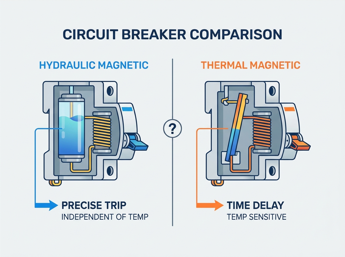
The most significant divergence between these technologies lies in their contrasting temperature profiles. Hydraulic magnetic breakers maintain a steady, flat-line current rating regardless of the surrounding air temperature. In contrast, thermal magnetic breakers exhibit a highly variable, temperature-dependent trip curve. As the environment gets hotter, the breaker trips faster and at lower currents; as it gets colder, it holds more current than rated, potentially allowing an overload to persist.
Designing panels with thermal magnetic breakers in environments that deviate from their standard calibration baseline requires complex engineering calculations and temperature derating mechanics. Engineers must consult derating tables to adjust the breaker's effective rating. For example, a 20A thermal breaker operating in a hot environment might effectively act as a 15A breaker. Failing to perform these calculations leads directly to nuisance tripping during peak summer months or in hot industrial facilities.
This sensitivity often triggers the runaway enclosure effect. When engineers install closely packed, heat-generating thermal magnetic breakers inside a sealed panel, the breakers heat each other. This compounding heating cycle artificially lowers the trip point of every breaker in the array. To compensate, designers are forced to oversize the breakers, increase the panel dimensions, or install active cabinet cooling systems, adding complexity and maintenance points.
Hydraulic magnetic temperature immunity simplifies panel design. The trip point of a hydraulic magnetic breaker remains at 100% of its rated current across a broad temperature envelope without derating. Because the magnetic field strength is unaffected by ambient heat, engineers can specify the exact breaker rating required for the load without applying derating formulas or worrying about adjacent breaker heating.
Feature | Thermal Magnetic Breaker | Hydraulic Magnetic Breaker |
|---|---|---|
Temperature Sensitivity | High (Requires derating) | None (100% rated across temp range) |
Internal Watt Loss | Higher (Bimetallic resistance) | Lower (Copper coil efficiency) |
Reset Time | Delayed (Requires cool-down) | Immediate |
Vibration Resistance | Lower (Susceptible to mechanical shock) | Higher (Stable latching mechanism) |
Orientation Sensitivity | None | High (Gravity affects core movement) |
An energy efficiency comparison reveals a distinct advantage for hydraulic designs. Thermal magnetic breakers consume more power during normal operation due to the continuous heating of the bimetal strip. While the watt loss per individual breaker might seem small, the cumulative effect in a distribution panel containing dozens of breakers becomes substantial and measurable.
This directly impacts enclosure thermal management. Specifying low-watt-loss hydraulic magnetic breakers quantifiably reduces the cooling requirements inside control cabinets. By eliminating the internal heat source of bimetallic strips, engineers can often downgrade or entirely remove cabinet fans and air conditioning units. This reduction in active cooling components increases the overall reliability of the entire control system.
Protection strategies require matching the breaker's trip profile to the load's behavior. Thermal magnetic breakers generally offer standardized trip curves. These rigid families provide limited flexibility, forcing engineers to fit their load profile into a pre-defined box, which can be problematic for specialized industrial equipment.
Hydraulic magnetic systems offer highly tailored trip curves. Manufacturers can alter the viscosity of the silicone fluid and the spring tension to create customized delay curves, including instantaneous, ultra-short, medium, and long delays. This allows for precise matching of the breaker to the specific application, ensuring protection without nuisance tripping.
Inrush current tolerance is a major factor in heavy industrial applications. High-amplitude, short-duration transient currents occur frequently during inductive load startups, transformer magnetization, and capacitive power supply charging. A precisely tuned hydraulic magnetic breaker handles these transients effortlessly by utilizing a specific fluid viscosity that prevents the core from moving fast enough to trip during the brief inrush phase.
Environmental stressors extend beyond temperature. When comparing vibration and shock resistance, thermal magnetic latches can be mechanically sensitive. Heavy machinery vibration, railway transit, or seismic activity can cause the delicate latching mechanism holding the bimetallic strip to release prematurely, causing a mechanical nuisance trip and stopping production.
Hydraulic magnetic breakers introduce their own physical constraints regarding mounting position and gravity effects. Because they rely on a spring-loaded moving core suspended in fluid, gravity plays a role in the core's resistance to movement. Mounting these breakers horizontally or upside down changes the gravitational force exerted on the iron core, which slightly alters the trip curve.
To mitigate this, engineers must apply orientation correction factors. If a hydraulic magnetic breaker is mounted in any orientation other than the standard vertical position, manufacturer-specified correction factors must be utilized to ensure the trip timing remains accurate. Some manufacturers offer specially balanced armatures to counteract this effect, but it remains a design consideration.

Following a fault, the speed of recovery dictates system availability. Thermal magnetic breakers impose thermal cool-down delays. After the bimetallic strip bends and trips the breaker, it remains physically deformed until it cools down and contracts back to its original shape. Attempting to force the breaker closed before this cooling period elapses will result in the breaker immediately tripping again.
Hydraulic magnetic breakers provide immediate reset capabilities. Because their operation relies on mechanical movement and magnetic fields rather than retained heat, the breaker can be reset instantly after the fault condition is cleared. This immediate operational recovery is highly valued in continuous process manufacturing and emergency power applications where every second of downtime costs money.
An upfront vs. operational cost analysis highlights the differing market positions of these devices. Thermal magnetic breakers benefit from massive economies of scale, resulting in a low initial unit cost. They are mass-produced for general-purpose applications. Hydraulic magnetic units are highly engineered, low-volume devices that carry premium pricing.
Footprint and panel density often offset the initial unit cost. Slim-line hydraulic magnetic breakers allow for higher circuit density per DIN rail foot. Because they do not generate significant heat, they do not require the ventilation gaps often mandated between thermal magnetic breakers. This allows engineers to use smaller, more compact enclosures, saving on sheet metal and wall space.
Regarding long-term service life, repeated tripping cycles degrade the calibration of bimetallic strips over time. The constant heating, bending, and cooling causes metal fatigue, eventually altering the trip point. Hydraulic magnetic cores, housed in hermetically sealed cylinders, provide stable, repeatable calibration over thousands of operations without degradation.
Thermal magnetic breakers remain the standard choice for ideal environmental profiles. They excel in climate-controlled industrial facilities, residential load centers, standard commercial building distribution boards, and standard HVAC equipment where ambient temperatures remain relatively stable and predictable year-round.
They fit perfectly within load and budget criteria that prioritize low upfront material costs. Applications featuring standard resistive loads or low-inrush inductive loads, where dynamic temperature fluctuations are non-existent, are best served by the cost-effective thermal magnetic design.
Hydraulic magnetic breakers are mandatory for harsh and high-temperature environments. Outdoor telecom enclosures, marine engine rooms, solar PV combiners, oil and gas field installations, and railway rolling stock experience extreme temperature swings that would render thermal breakers dangerously inaccurate and prone to nuisance tripping.
They are equally critical for mission-critical applications. High-density datacenters, military mobile power units, emergency medical systems, and remote industrial automation panels demand absolute uptime. In these scenarios, the zero-derating characteristics and immediate reset capabilities justify the premium investment.
Highly dynamic load profiles necessitate hydraulic magnetic technology. Large industrial motors, heavy compressors, and high-frequency transformers require specific, customized time-delay curves to survive massive high-inrush startup phases without tripping, while still maintaining tight protection during steady-state operation.
While immune to heat derating, hydraulic magnetic breakers face the extreme cold fluid variable. In sub-zero environments, typically below -40°C, the viscosity of the silicone fluid inside the dashpot increases. This thickening slows the movement of the iron core, which can inadvertently lengthen the trip times during moderate overloads.
The primary mitigation strategy involves specifying low-viscosity or arctic-grade fluid damping variations. Manufacturers offer specialized fluid fills designed specifically for polar deployments, ensuring the time-delay curve remains accurate even in deep freeze conditions.
Compact control cabinets often introduce the horizontal mounting risk. Physical layout changes may force DIN rails to be run vertically, requiring breakers to be mounted flat on their sides. This alters the gravitational pull on the hydraulic core and changes the trip characteristics.
Identify the exact mounting angle of the breaker within the enclosure.
Consult the manufacturer's datasheet for specific orientation derating multipliers.
Apply the correct manufacturer-supplied orientation derating factors to the load calculations.
Specify a specially balanced armature hydraulic breaker if standard derating is not feasible.
Regulatory standards alignment is a strict requirement during implementation. Engineers must ensure correct selection between branch circuit protection standards, such as UL 489, CSA C22.2 No. 5, and IEC 60947-2, versus supplementary protector standards like UL 1077 and IEC 60898. Mixing these up violates electrical codes and voids panel certifications.
Physical retrofitting challenges also arise when substituting breaker types in legacy panels. Engineers must evaluate terminal busbar configurations, terminal height variations, and mounting clip compatibility, as hydraulic magnetic breakers often feature different physical dimensions than their thermal magnetic counterparts.
The choice between a hydraulic magnetic vs thermal magnetic circuit breaker requires determining which technology aligns with the thermal stability, physical mounting constraints, and criticality of the target environment. Thermal magnetic breakers remain the best choice for cost-driven, stable ambient conditions and standard non-critical loads. Hydraulic magnetic breakers are mandatory for extreme or fluctuating temperatures, high-density panels, high-vibration applications, and mission-critical systems requiring immediate uptime recovery.
CHINEHOW provides circuit protection solutions designed to support industrial control, power distribution, communication equipment, and other demanding electrical applications. Its product selection helps engineers balance protection accuracy, environmental adaptability, installation requirements, and long-term system reliability.
Conduct a comprehensive panel thermal audit using infrared thermography to determine the true operating temperature inside your enclosures.
Review manufacturer time-current characteristic curves to match the breaker precisely to your load's specific inrush profile.
Analyze your physical mounting orientations and apply necessary correction factors if using hydraulic magnetic units horizontally.
Consult with an applications engineer before ordering replacement inventory to verify regulatory compliance and physical fitment.
A: The primary advantage is absolute temperature immunity. They require no temperature derating, offer highly precise and customizable trip curves, allow for immediate reset post-trip, and generate minimal internal heat compared to thermal alternatives.
A: Yes. Because they rely on heat to trip, operating them in environments hotter than their calibration baseline requires derating calculations to prevent nuisance tripping.
A: Not without consideration. Because they use a moving core in fluid, gravity affects their operation. Mounting them horizontally or upside down requires applying manufacturer-specified correction factors or using specially balanced models.
A: The internal bimetallic strip physically bends due to heat during an overload. It must be allowed time to cool and contract back to its original shape before the breaker mechanism can be successfully reset.
A: Yes, they carry a higher upfront unit cost due to their complex construction. However, they often save money long-term in harsh environments by preventing downtime and eliminating the need for active panel cooling.
A: Hydraulic magnetic breakers generally perform better in high-vibration environments, as the delicate latching mechanisms of thermal magnetic breakers are more susceptible to mechanical shock and vibration-induced nuisance trips.


