
Views: 0 Author: Site Editor Publish Time: 2026-09-22 Origin: Site


Incorrect circuit protection specification carries severe operational and safety stakes. Specifying the wrong breaker leads to nuisance tripping, accelerated equipment degradation, and catastrophic fire hazards. Engineers face a constant challenge balancing specific load requirements, such as resistive versus highly inductive profiles, against environmental constraints, safety standards, and facility architecture. A mismatched component compromises the entire electrical network.
You must evaluate multiple technical parameters to ensure reliable operation and fault clearance. We will introduce a strict technical framework for evaluating and specifying the correct miniature circuit breaker. This involves analyzing nominal current ratings, specific tripping characteristics, maximum breaking capacity, and precise pole configurations based on the installation environment. We base this framework on real-world field conditions, bypassing theoretical assumptions to focus on practical load calculations and environmental derating.
Trip curves dictate application: Selecting between Type B, C, or D curves depends entirely on the load's inrush current profile (resistive vs. highly inductive).
Breaking capacity is non-negotiable: The miniature circuit breaker’s short-circuit capacity must exceed the maximum prospective fault current at the point of installation to prevent catastrophic failure.
Pole configuration must match network architecture: Selection between 1P, 2P, 3P, and 4P depends on the earthing system and whether neutral isolation is required.
Environmental derating impacts rating: Ambient temperature, altitude, and enclosure density require recalculation of the nominal current rating.
Table of Contents
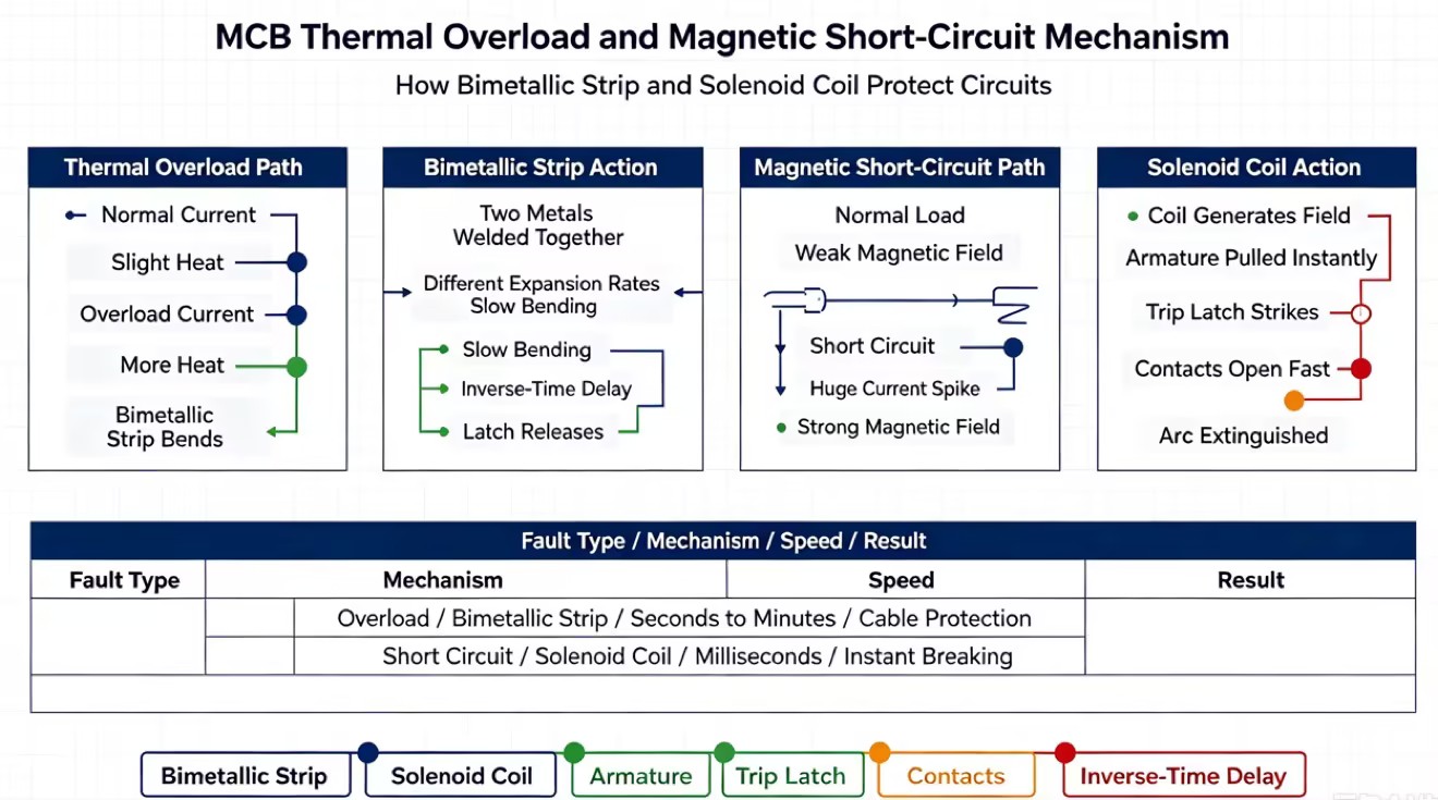
Electrical networks require a dual-protection mandate to operate safely. You must protect cables and connected equipment from two distinct fault conditions: sustained thermal overloads and instantaneous short circuits. A thermal overload occurs when a circuit draws slightly more current than its rated capacity for an extended period. This slowly degrades cable insulation, eventually leading to a breakdown. A short circuit is an immediate, massive surge in current caused by a direct phase-to-neutral or phase-to-earth fault. The correct Miniature Circuit Breaker handles both scenarios seamlessly. It isolates the fault before thermal damage or electrical fires occur. Field engineers know that relying on fuses for this dual role often leads to inconsistent protection and extended downtime during replacement. A mechanical breaker provides resettable, calibrated protection.
Protection against low-level, sustained overloads relies on a bimetallic strip inside the breaker. This strip consists of two different metals welded together. Each metal possesses a different coefficient of thermal expansion. As current flows through the strip, normal operating currents generate minimal heat. When an overload occurs, the excess current generates significant heat. The bimetallic strip bends as the metals expand at different rates. This bending action is intentionally slow. It provides an inverse-time delay. A minor overload might take minutes to trip the breaker. This allows for temporary, harmless surges like starting a small fan. A larger overload bends the strip faster, tripping the latch mechanism in seconds to cut the power.
Short circuits require instantaneous intervention. The bimetallic strip reacts too slowly to prevent the explosive energy of a dead short. For this, the breaker utilizes a magnetic tripping mechanism centered around a solenoid coil. Under normal load conditions, the magnetic field generated by the coil is too weak to move the internal armature. When a short circuit strikes, the current spikes to hundreds or thousands of amps in milliseconds. This massive current creates a powerful magnetic field. The field instantly pulls the armature, striking the trip latch and forcing the contacts open. This action extinguishes the fault in a fraction of a second. It prevents catastrophic wire melting and equipment destruction.
Protection Type | Internal Mechanism | Response Time | Target Fault Condition |
|---|---|---|---|
Thermal Overload | Bimetallic Strip | Inverse-time delay (seconds to minutes) | Sustained overcurrents, overloaded circuits |
Magnetic Short Circuit | Solenoid Coil / Armature | Instantaneous (milliseconds) | Dead shorts, phase-to-phase faults |
Determining the normal operating current is the first mathematical step in specification. You calculate this based on the total connected load wattage and the system voltage. For a standard single-phase resistive load, the formula is straightforward. Current equals power divided by voltage. For three-phase systems or inductive loads, you factor in the power factor and the square root of three. Accurate load calculation prevents baseline sizing errors. You account for all devices operating simultaneously on the circuit to establish the true continuous load profile. Guessing the load based on square footage or historical rules of thumb leads to undersized breakers and constant nuisance tripping.
Standard engineering practice dictates that continuous loads should not exceed 80% of the breaker’s nominal rating. A continuous load is defined as any load operating at maximum current for three hours or more. If a circuit draws a continuous 16 amps, you do not install a 16A breaker. Operating a breaker at 100% capacity continuously generates internal heat. This pushes the bimetallic strip close to its tripping threshold. It causes nuisance trips during minor ambient temperature fluctuations. Applying the 80% rule ensures thermal stability. For a 16A continuous load, you divide by 0.8 to find the minimum breaker size, which is 20A.
Manufacturers produce these devices in standardized current ratings. You cannot order a custom 17.5A breaker. Common standard ratings include 6A, 10A, 16A, 20A, 32A, 40A, 50A, and 63A. High-capacity models scale up to 80A, 100A, and 125A. Once you calculate your required current and apply the 80% rule, you select the next highest standard size. If your calculation dictates a 27A requirement, you specify a 32A miniature circuit breaker. Selecting a rating too close to the calculated load risks unwanted tripping. Selecting one too high compromises the thermal protection of the downstream cables.
The nominal rating printed on the breaker assumes a specific ambient temperature, typically 30°C. Installation environments often deviate from this baseline. This requires mathematical derating to ensure the breaker performs as expected under field conditions.
Derating Factor | Environmental Condition | Impact on Breaker Rating |
|---|---|---|
Ambient Temperature | Exceeding 30°C calibration point | Reduces current carrying capacity. Requires higher nominal rating selection to prevent premature thermal tripping. |
High Altitude | Installations above 2000 meters | Reduces cooling efficiency and dielectric strength. Derates both current carrying capacity and maximum voltage ratings. |
Mutual Heating | Multiple breakers mounted adjacently | Restricts airflow. Requires applying a grouping factor multiplier (e.g., 0.8) to account for shared thermal load. |
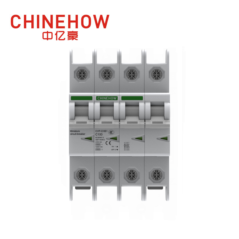
Type B curves are designed for purely resistive loads or circuits with very low inrush currents. The magnetic trip mechanism activates when the current reaches between 3 and 5 times the rated current. You specify Type B for residential lighting, standard resistive space heaters, and long cable runs. In long cable runs, fault currents might be relatively low due to high cable impedance. Using a Type B breaker on a motor load guarantees immediate nuisance tripping the moment the motor starts.
The Type C curve serves as the standard choice for most commercial and industrial applications involving moderate inductive loads. It trips instantaneously at 5 to 10 times the rated current. This delay allows small motors, fluorescent lighting ballasts, and standard control circuits to draw their necessary startup current without interrupting power. If you are protecting standard power outlets in an industrial facility where users might plug in power tools or small compressors, Type C provides the necessary balance between inrush tolerance and rapid fault clearance.
Highly inductive loads demand a Type D curve. These loads generate massive inrush currents that can last for several cycles. The magnetic trip is calibrated to activate only when current spikes between 10 and 20 times the nominal rating. You specify Type D for heavy electric motors, large transformers, industrial welding equipment, and X-ray machines. While Type D prevents nuisance tripping during aggressive startups, it requires careful verification of the circuit's earth fault loop impedance. You must ensure the breaker will still trip quickly enough during a genuine short circuit.
Certain industrial applications require highly specialized tripping characteristics beyond the standard B, C, and D profiles. You must match these curves to the exact tolerance of the connected equipment.
Type Z (2-3x In) and Type A: These curves are ultra-sensitive. They trip at 2 to 3 times the rated current. You use them to protect highly sensitive semiconductor devices, programmable logic controllers, and delicate electronic measuring circuits. Even a minor, brief overcurrent could destroy these silicon components.
Type K (8-12x In): The Type K curve is optimized for specialized motor and transformer protection. It offers a slightly tighter tolerance than Type D. This provides aggressive protection for motor windings while still allowing for significant magnetic inrush currents.
Curve Type | Magnetic Trip Threshold | Typical Field Application |
|---|---|---|
Type B | 3 to 5 times In | Resistive loads, long cable runs, residential lighting circuits |
Type C | 5 to 10 times In | Moderate inductive loads, small motors, commercial power outlets |
Type D | 10 to 20 times In | Heavy inductive loads, transformers, industrial welding machines |
Type Z / A | 2 to 3 times In | Highly sensitive electronics, PLCs, semiconductor protection |
Type K | 8 to 12 times In | Specialized motor and transformer winding protection |
Breaking capacity represents the absolute maximum fault current the breaker can safely interrupt without sustaining physical damage, welding its contacts, or failing to clear the fault. This is measured in kiloamps (kA). When a short circuit occurs, the current bypasses the normal load resistance and spikes massively. Residential applications typically require a 6kA breaking capacity. Industrial environments, with larger transformers and thicker supply cables, routinely require 10kA, 15kA, or even 25kA capacities. Specifying the correct breaking capacity is a strict safety mandate.
Understanding the distinction between testing standards is vital for industrial specification. Ics or Icn indicates the maximum current the breaker can interrupt safely and remain fully operable for continued use. Icu defines the absolute maximum fault current the device can interrupt safely once. If a breaker clears a fault at its Icu rating, it has successfully prevented a fire. However, the internal contacts and arc chutes are likely destroyed. This requires immediate replacement of the unit. You design systems so that expected faults fall within the Ics rating.
You cannot guess the required breaking capacity. You calculate the Prospective Short-Circuit Current (PSCC) at the specific point of installation. The PSCC is the maximum potential current that would flow if a dead short occurred right at the breaker's output terminals. This calculation relies on the size of the upstream supply transformer and the total impedance of the cables running from the transformer to the distribution board. Larger transformers and shorter, thicker cables result in a much higher PSCC. The selected Miniature Circuit Breaker must have a kA rating strictly greater than the calculated PSCC.
Installing a breaker with a 6kA capacity in a location with a 10kA PSCC guarantees catastrophic failure during a short circuit. The internal arc chutes will fail to extinguish the electrical arc generated as the contacts open. The intense heat will weld the contacts together. This allows the massive fault current to continue flowing downstream. It leads to immediate cable insulation fires, potential arc flash explosions, and the physical rupture of the plastic enclosure. Undersizing breaking capacity is a severe violation of electrical safety codes.
Single-pole breakers are the standard choice for basic 230V single-phase circuits. They switch only the live phase conductor. The neutral remains solidly connected at the terminal bar. Single-Pole + Neutral devices occupy the same physical space or slightly more, but they switch both the phase and the neutral. In an SPN device, only the phase conductor contains thermal-magnetic protection. The neutral pole is merely an isolation switch that opens simultaneously. You use SPN when local regulations require complete isolation of the circuit for maintenance.
Double-pole breakers switch both the phase and the neutral. Both poles contain thermal and magnetic protection mechanisms. You specify 2P breakers in single-phase systems where there is a high risk of neutral faults. They are also used in specific IT earthing systems where the neutral is not referenced to earth. If a fault causes the neutral to become energized at a dangerous voltage, a 2P breaker ensures the fault is detected and both conductors are safely disconnected from the supply.
Three-pole configurations are utilized exclusively for standard 400V three-phase loads that do not require a distributed neutral. The most common application is three-phase industrial motors. The breaker monitors all three phase conductors simultaneously. If an overload or short circuit occurs on any single phase, the internal mechanical linkage ensures all three poles trip together. This simultaneous tripping prevents the motor from single-phasing. Single-phasing rapidly overheats and destroys motor windings.
Four-pole and Three-Pole + Neutral breakers handle three-phase systems that include a neutral conductor. TPN devices protect the three phases while providing a switching, non-protected neutral pole for isolation. True 4P breakers provide thermal-magnetic protection on all four poles. You specify 4P breakers for three-phase unbalanced loads where significant harmonic currents might overload the neutral conductor. They are also used in environments where strict isolation rules demand the complete disconnection of all live conductors during a fault.
Pole Configuration | Protected Poles | Switched Poles | Primary Use Case |
|---|---|---|---|
1P (Single-Pole) | Phase only | Phase only | Standard 230V single-phase circuits with solid neutral |
SPN (Single-Pole + Neutral) | Phase only | Phase and Neutral | Single-phase circuits requiring neutral isolation for maintenance |
2P (Double-Pole) | Phase and Neutral | Phase and Neutral | Single-phase systems with high neutral fault risk or IT earthing |
3P (Three-Pole) | All 3 Phases | All 3 Phases | Standard 400V three-phase motor loads without distributed neutral |
4P (Four-Pole) | All 3 Phases + Neutral | All 3 Phases + Neutral | Three-phase unbalanced loads or strict complete isolation requirements |
The rated working voltage of the breaker must be strictly greater than or equal to the maximum operating voltage of the line. Installing a device rated for 230V on a 400V circuit compromises the internal insulation and the arc extinguishing capabilities. During a fault, the higher voltage can cause the electrical arc to jump across the open contacts. This sustains the short circuit. You verify the system voltage and ensure the chosen component is certified for that specific voltage class.
Alternating Current and Direct Current behave entirely differently during a fault. AC voltage naturally crosses zero volts 50 or 60 times a second. AC breakers rely on this zero-crossing point to help extinguish the electrical arc drawn when the contacts open. DC voltage never crosses zero. It provides a continuous, relentless supply of energy. If you use a standard AC breaker on a DC circuit, such as a solar PV array or a battery storage system, the internal arc chutes will fail to break the DC arc. The arc will sustain, melt the contacts, and cause a fire. You specify dedicated DC-rated breakers equipped with specialized magnetic blowouts to force the DC arc into the extinguishing chamber.
Calculate the exact Prospective Short-Circuit Current (PSCC) at the distribution board using the transformer kVA and cable impedance data before selecting the breaking capacity.
Audit the facility's single-line diagram to verify that the selected trip curves coordinate properly with upstream protection devices to ensure full selectivity.
Review the manufacturer's technical data sheets to apply the correct derating factors for ambient temperature, altitude, and adjacent mounting density.
Verify that the physical terminal capacity of the selected breaker matches the required cable cross-section specified in your wiring schedule.
A: The primary difference lies in current capacity and adjustability. Miniature circuit breakers typically handle currents up to 125A and have fixed trip settings. Molded Case Circuit Breakers handle much larger loads, up to 2500A. They usually feature adjustable thermal and magnetic trip settings, allowing engineers to fine-tune protection for complex industrial networks.
A: Your choice depends entirely on the inrush current magnitude of the specific load. Use Type C for standard inductive loads like small motors and fluorescent lighting, which draw 5 to 10 times their rated current on startup. Use Type D for heavy inductive loads like transformers and large industrial motors that draw 10 to 20 times their rated current.
A: If the prospective short-circuit current exceeds the breaker's breaking capacity, the internal arc chutes cannot extinguish the electrical arc. The intense heat will weld the internal contacts closed, allowing massive fault currents to continue flowing. This leads to immediate cable fires, enclosure rupture, and catastrophic failure of the electrical system.
A: No. Oversizing the breaker creates a severe safety risk. The breaker is sized to protect the downstream cable. If you install a 40A breaker on a cable rated for 20A, a sustained 35A overload will melt the cable insulation and start a fire long before the oversized breaker detects a fault and trips.
A: Industrial environments typically require breaking capacities between 10kA and 25kA under the IEC 60947-2 standard. This is significantly higher than the 6kA capacity standard for residential applications. Industrial facilities have larger supply transformers and lower cable impedances, which generate much higher prospective fault currents.
A: No. They only protect against overcurrents and short circuits between live conductors. They do not detect small leakage currents to earth. To protect personnel from electric shocks and detect earth faults, you must install Residual Current Devices (RCDs) or use Residual Current Breakers with Overcurrent (RCBOs).
A: No. AC voltage naturally crosses zero volts multiple times a second, which helps extinguish the arc when the breaker opens. DC current has no zero-crossing point, making the arc much harder to break. Standard AC breakers will fail to extinguish a DC arc, resulting in contact welding and severe fire hazards.


